Triggering
Flexible Triggering

With mixed analog and digital designs, sometimes it is hard to trace an anomaly back to its root cause unless you can trigger

on it and correlate it with another signal. With the 54600-Series scopes, triggering is no longer a hassle. They come with

flexible triggering capabilities across all channels so you can easily isolate and analyze complex signals and interactions

common in your mixed analog and digital designs.

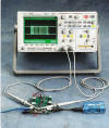
Easily synchronize to a USB packet.

¡@
CAN, and USB Triggering

Controller Area Network (CAN) and Universal Serial Bus (USB) triggering comes standard with the 54600-Series scopes.

These triggering modes make it easy to synchronize CAN, and USB frames. Don¡¦t waste time finding the start of the complex

frames.

¡@

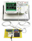
CAN triggering synchronizes to the start of a CAN frame on any CAN high or CAN low signal.

¡@

USB is quickly becoming the connection of choice for PC peripherals. Make your testing easy with Start of  Packet (SOP),

End of  Packet (EOP), Reset Complete (RC), Enter Suspend, or Exit Suspend modes.

Make your automotive and industrial testing easier. CAN triggering synchronizes to the start of a CAN frame

on any CAN high or CAN low signal.

¡@ ¡@
I2C and SPI Triggering

Don¡¦t spend your time sorting through communication frames to find the one of interest. Let Agilent set up an Inter-Integrated
Circuit (I2C) or Serial Peripheral Interface (SPI) trigger to sift through the frames for you. And like the CAN, and USB triggers,
I2C and SPI come standard with the 54600-Series scopes.

The full range of I2C triggering includes start or stop condition, missing acknowledge, restart, EEPROM data read, address
and/or data frame, or 10-bit write. SPI triggering allows for trigger on user-definable framing and user-definable number of bits
per frame, as well as data patterns.

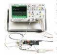
 Trigger on data patterns within a SPI frame. Trigger on address and/or data patterns within an I2C frame. 
¡@
Microcontroller and DSP Applications

Microcontrollers (MCUs) and Digital Signal Processors (DSPs) are here to stay, and are becoming more pervasive in  industrial,
communications, automobile, and consumer products. Design engineers must grapple with scopes that were not developed to
tackle the mixed analog and digital signals found in MCU- and DSP-based designs. Many engineers, who rely primarily on
typical 2-channel or 4-channel scopes in mixed analog and digital signal verification and debug, find these scopes to be
inadequate when it comes to the channel count, memory depth, display and triggering. The interactions that occur in typical
mixed analog and digital design ¡X taking a realworld signal such as audio, video, temperature or pressure, performing some
transformation on the signal, and finally returning that signal to the real world ¡X require more viewing capability than current 

scopes can provide.

¡@

Agilent 54621D, 54622D, 54641D, and 54642D mixed-signal oscilloscopes (MSOs) provide the channel count, memory depth,
high-definition display, and triggering that MCU and DSP designs demand.

The 350 MHz and 500 MHz MSOs are a great fit for DSP applications.

¡@

Model Bandwidth Maximum Sample Rate Maximum Memory* Channels
54621A 60 MHz 200 MSa/s 4 MB 2
54621D 60 MHz 200 MSa/s 4 MB 2+16
54622A 100 MHz 200 MSa/s 4 MB 2
54622D 100 MHz 200 MSa/s 4 MB 2+16
54624A 100 MHz 200 MSa/s 4 MB 4
54641A 350 MHz 2 GSa/s* 8 MB 2
54641D 350 MHz 2 GSa/s* 8 MB 2+16
54642A 500 MHz 2 GSa/s* 8 MB 2
54642D 500 MHz 2 GSa/s* 8 MB 2+16

¡@

Probes and Accessories

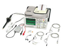
To get the most out of your scope, you need the right

probes and accessories for your particular application.
That's why Agilent Technologies offers a complete family

of innovative probes and 54600-Series scopes. For more
comprehensive information, please see the Agilent

54600-Series Oscilloscopes Probes and Accessories
data sheet (Agilent publication number 5968-8153). You

can get a copy by calling 1-800-452-4844 orby visiting
our website at:
www.agilent.com/find/mso

¡@
Agilent Passive Probes Selection Guide
¡@

10070C

¡@

10073C (shipped with

54640-Series)

10074C (shipped with

 54620-Series)

10076A

high-voltage probe

N2771A

high-voltage probe

Probe Bandwidth 20 MHz 500 MHz 150 MHz 250 MHz 50 MHz
Probe Risetime (Calculated) < 17.5 ns < 700 ps < 2.33 ns < 1.4 ns < 7 ns
Attenuation Ratio 1:1 10:1 10:1 100:1 1000:1

Input Resistance

(when terminated into 1 MΩ)

1 MΩ 2.2 MΩ 10 MΩ 66.7 MΩ 100 MΩ
Input Capacitance Approx. 70 pF Approx. 12 pF Approx. 15 pF Approx. 3 pF Approx. 1 pF

Maximum Input (dc + peak ac)


¡@

¡@

400 Vpk CAT I

(mains isolated)

400 Vpk CAT II

(post receptacle mains)

500 Vpk CAT I 

(mains isolated)

400 Vpk CAT II

(post receptacle mains)

500 Vpk CAT I

(mains isolated)

400 Vpk CAT II

(post receptacle mains)

4000 Vpk

¡@

¡@

¡@

15 kV dc, 10 kVrms

30 kV dc + peak ac

¡@

¡@

Compensation Range None 6 - 15 pF 9 - 17 pF 6 - 20 pF 7 - 25 pF
Probe Sense No Yes Yes Yes No

¡@

Current Probes Description
1146A 100 kHz current probe, ac/dc
N2774A 50 MHz current probe, ac/dc
N2775A power supply for N2774A
Differential Probes Description
N2772A 20 MHz differential probe
N2773A Differential probe power supply