MWJ-6392E DVD Jitter Meter
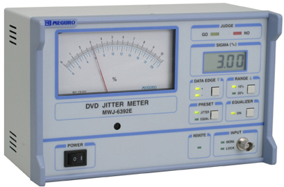

mwj6392e

The MWJ-6392E is designed for measuring and indicating the jitter components of the data signals with internal PLL clock signal employed as a reference signal from RF signals of DVD, DVD-ROM and other relative devices.
It indicates the measured jitter values by percent (%) in the SIGMA mode and can select either + , - or + /- edge of the data signals as the reference trigger clock edge.
It has the digital equalizer circuit which is adjustable according to the characteristics of Pick-ups, and the INHIBIT function is provided to inhibit jitter measurement of faulty section.
In addition, it indicate whether measured values are acceptable or not by GO or NO-GO lamp by presetting a criterion value.

FEATURES

―

It has the digital equalizer circuit which is adjustable according to the characteristics of Pick-up.

―

The jitter quantity can be directly read by the meter and LCD indicator.

―

This unit converts a time difference between a data signal and the clock into a sigma value and indicated its jitter quantity as the percentage to the clock cycle on the meter indicator.

―

Changes in the jitter can be read continuously, due to T/V conversion method of measurement.

―

It can select either + or -edge of the data (EFM Plus) signal as the trigger edge, and also select +, - or +/- edge for jitter measurement.

―

The INHIBIT function is provided to inhibit jitter measurement of faulty section.

―

A GO/NO-GO result is indicted in relation to a preset jitter value.

―

The panel-lock function is provided to set measuring conditions.

―

A remote control function is provided.

SPECIFICATIONS

 Input Section

DATA Input Signal

EFM Plus signal (RF or Binary signal)

Input Impedance

Approx. 1M�[, unbalanced

Input Capacity

25pF or less

Input Signal Level

0.1Vp-p to 2Vp-p

Clock Frequency Range

25.5 to 28.5MHz

INHIBIT Input Signal

TTL level

 Jitter Measurement

Indication

Percent(%) indication by the meter and LCD display in SIGMA mode

Measuring Range

0 to 10% and 0 to 20% in two ranges

Jitter Measuring Range

〉0.5T to the clock edge

Measuring Accuracy

• Meter Display

〉5% of full scale

• Digital Display

〉(3% of reading +20 digits), Min. resolution; 0.01%

• Reference Clock

Internal PLL clock

Measuring Data Edge

+,-, or + /-(selectable)

Equalizer (only for RF)

• Frequency Characteristics

In conformity to JIS}6241

• Standattird Seng

+3.2dB 〉0.3dB (5.16MHz -200kHz @27MHz)

• Range

0 to 7dB 0.2dB step

• Group Delay Characteristics

Max. 5ns

Low Pass Filter Characteristics

6th Bessel Fc = 8.46 MHz

Slicer Characteristics

In conformity to JIS}6241

PLL Characteristics

In conformity to JIS}6241

 Output Section

RECORDER Output

1VDC 〉5% at full scale with open end

MONITOR Output

-6dB 〉1dB to input signal level at 50�[ load

REMOTE Output

DATA EDGE, RANGE, EQUALIZER on/off modes on the panel are externally controlled

 Optional output terminals on the rear panel

EQUALIZER Output

Approx. 0.65 V p-p at 50�[ load

JITTER Output

0.1 V rms. 〉10% at 50�[ load

DATA Output

0.5 V p-p at 50�[ load

CLOCK Output

0.5 V p-p at 50�[ load

 General Data

Operating temperature range

+5ºC to +40ºC

Power requirements

AC 100/120V to 220/240V ; 15VA

Dimensions

Approx. 240(W)}154(H)}130(D) mm

Weight

Approx. 2.05kg

*

Specifications are subject to change without notice.
