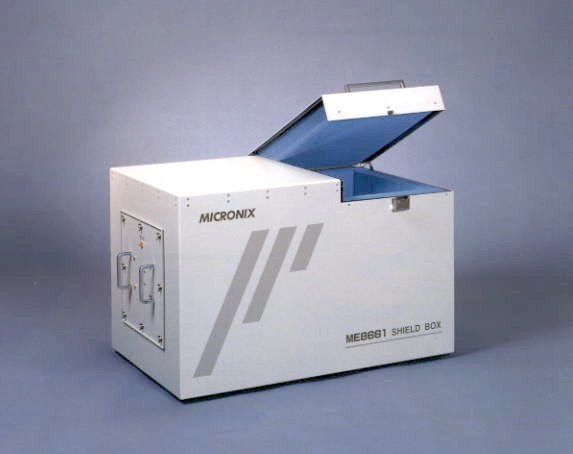
Shielding box (electromagnetic anechoic box) ME8661
Optimum for testing W-CDMA, CDMA, GSM, PDC, PHS, ETC and wireless systems. A receiving antenna of your choice will be mounted.
This is a simple type shielding box that may be used on a desk. It is of triple structure, i.e., radio wave absorber, copper plate and aluminum plate. It covers the frequency band of low frequency through 18GHz. Furthermore, an acrylic resin table for placing a test sample is provided, and this structure permits easy mounting of an optional receiving antenna.
820 (W) × 500 (H) × 500 (D) mm
Applications
Application 1 Wireless system test
With a W-CDMA, CDMA, GSM, PDC, PHS, OBE of ETC, wireless LAN, Bluetooth and wireless communication equipment, it is possible to test the wireless system in a free space that is close to actual working conditions (testing of transmission power, transmission frequency, spurious, occupied bandwidth, carrier-off leakage power, adjacent channel power, modulation factor, transmission eye pattern, etc.).
This wireless system test is done in the state where a test sample is placed on the acrylic resin table (200 mm × 200 mm) in ME8661 as shown above, a receiving antenna is mounted in a position that is opposed to the test sample the output of a receiving antenna is connected to a spectrum analyzer, microwave wattmeter or the like. Therefore, an optional receiving antenna is needed for conducting this test. Two optional receiving antenna models, i.e., Model A and Model B, are available. It is, however, also possible to mount an antenna of different specification, if the frequency band and polarization are appropriately specified. A distance of 30 cm or greater may be provided between the test sample and the receiving antenna. An optional reference antenna is used for calibration of RF coupling degree (loss between front face of test sample and SMA connector of receiving antenna output). Antenna gain and frequency characteristics data of RF coupling degree are appended to this reference antenna. Although the antenna itself is the same whether a reference antenna or a receiving antenna, a reference antenna is provided with a fixing stand made of acrylic resin, so that it can be placed on the acrylic resin table.
Reference antenna A |
Frequency range : 2
to 18GHz |
|
Reference antenna B |
Frequency range : 2
to 5GHz |
Application 2 Antenna test
Connect a signal source to the reference antenna connector and connect a measuring instrument to the receiving antenna connector. Having done this, antenna characteristics data can be acquired.
Application 3 Electromagnetic anechoic box
Capable of using as a mere electromagnetic anechoic box without mounting antenna. It is optimum for simple preliminary experiments for EMC testing and when it is wanted to conduct a test shielded from the external magnetic field.
Specifications
| Outside dimensions | 820 (W) × 500 (H) × 500 (D) mm |
| Inside dimensions | 700 (W) × 380 (H) × 380 (D) mm |
| Structure | Triple structure composed of radio wave absorber, copper plate and aluminum plate |
| Weight | approx. 38kg (excluding antenna) |
| Acrylic resin table | 200 × 200 mm |
| Connectors | SMA (3pcs) (reference side 1pc, receiving side 2pcs) 25 pins D-sub connector 1pc |
Products list | brand | Model No. | Home