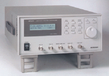
MFG206 Arbitrary Function Synthesizer
MFG206 , 1mHz to 20MHz / 30Vp-p (at open load) Highly accurate and stable frequency due to synthesized method Formation of arbitrary waveform with Windows computer

Equipping with Dual Functions of Function Synthesizer and Arbitrary Waveform Generator
Features of MFG206
1. 1mHz to 20MHz
/ 30Vp-p (at open load)
2. High accuracy and stability of frequency due to synthesizing method
3. Arbitrary waveform generator function (10Mwords / s, 12bits, 128Kwords)
4. BURST / GATE functions
5. Dual functions of linear and logarithmic sweep
6. Wide application due to VCF function
7. RS-232C (standard) and GP-IB (optional)
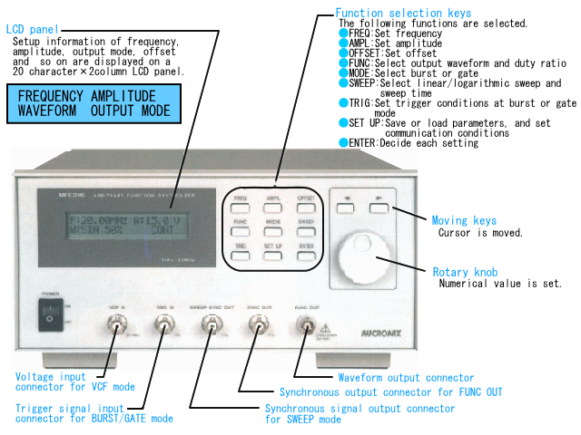
¡@
¡@
¡@
¡@
¡@
¡@
¡@
¡@
¡@
¡@
¡@
¡@
¡@
¡@
¡@
¡@
¡@
¡@
¡@
¡@
¡@
¡@
¡@
¡@
¡@
¡@
¡@
¡@
¡@
¡@
¡@
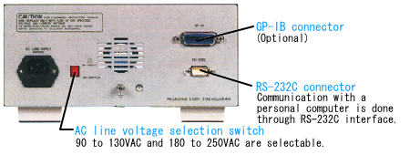
¡@
¡@
¡@
¡@
¡@
¡@
¡@
¡@
¡@
Simplified and low-cost design with high accuracy, high stability, and dual functions
The model MFG206 synthesizer is a function generator equipped with a phase-locked loop (PLL) circuit that is capable of generating a highly accurate and stable frequency. The arbitrary function synthesizer can be used for the following applications : (1) A function synthesizer that can generate sine, triangle, or square wave in the wide bandwidth of 1mHz to 20MHz with a wide amplitude, as high as 30Vp-p at open load. (2) A 12-bit and 128K-word arbitrary waveform generator that has a sampling frequency of 10MHz maximum. The model MFG206 synthesizer is a superb function generator having high signal accuracy and stability despite its simplified and low cost design, whose superior cost effectiveness justifies its uses for many applications.
![]() Wide amplitude : 30Vp-p
Wide amplitude : 30Vp-p
The synthesizer can output a signal that has wide amplitude, as high as 30Vp-p
at open load. The maximum amplitude is 15Vp-p when it is terminated with a
50-ohm load.
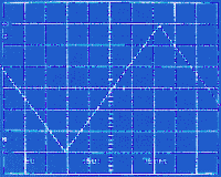
Triangle wave, 30Vp-p output
¡@
![]() Synthesizing
method
Synthesizing
method
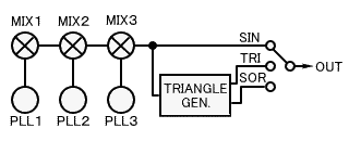
The synthesizer generates the sine wave by means of the three pairs of PLL
circuits (PLL1, PLL2, and PLL3) and frequency mixers (MIX1, MIX2, and MIX3). The
triangle and square waves are generated based on the PLL circuit formed between
the sine wave as a reference frequency and the triangle wave generator as a
voltage control oscillator.
As stated above, all the three waveforms are output as highly stable wave
signals that are phase-locked by the reference crystal oscillator.
Burst and gate functions
![]() Burst or gated waveform can
also be output in addition to the continuous waves.
Burst or gated waveform can
also be output in addition to the continuous waves.
(1) Burst
The synthesizer can output a given waveform having a specified cycle number (1
to 4096) starting from the predetermined phase (-90¢X to +90¢X with 1¢X step).
The wave output begins at the rising edge of the TRIG input pulse or at the
manual operation. The burst waves can be output in the frequency range of
0.100Hz to 999.9kHz.
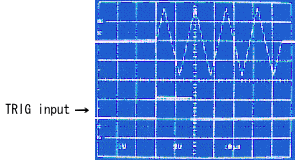
Burst wave (phase : 45¢X, 4cycles)
¡@
(2) Gate
The wave is output at the predetermined phase (-90¢X to +90¢X with 1¢X step)
when TRIG input reaches the high level. The wave output stops at the
predetermined phase after TRIG input reaches the low level.
The gated wave can be output in the frequency range of 0.1000Hz to 999.9kHz.
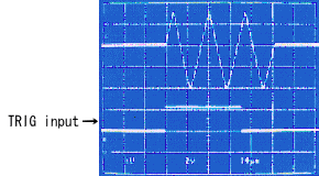 Gated
waveform (phase : 0¢X)
![]() Sweep
Sweep
The frequency can be swept up to the ratio of 1 : 100 by setting the start and
stop frequencies. The sweep time can be set within the range of 0.01 to 10
seconds. It is also possible to select the sweep mode, either to the linear
sweep or logarithmic sweep mode. In addition, the SWEEP SYNC output synchronized
with the sweep is also available. This is a very convenient function. The four
sweep ranges (200kHz to 20MHz, 10kHz to 1MHz, 1kHz to 100kHz and 100Hz to 10kHz)
will be automatically selected after setting the start and stop frequencies. An
error message will be displayed on the LCD unit if the two frequencies are set
beyond the specified sweep frequency range.
Example : Start frequency : 20kHz / Stop frequency : 2MHz ¡÷ Error message
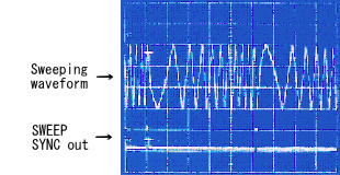 Sweeping
waveform
¡@
![]() VCF input
VCF input
A frequency is output, which is proportional to the voltage applied to the VCF
input. The dynamic range is approximately 1 : 100. Six sweep ranges are
available (200kHz to 20MHz, 10kHz to 1MHz, 1kHz to 100kHz, 100Hz to 10kHz, 10Hz
to 1kHz, and 1Hz to 100Hz).
Example : 10V ¡÷ 20MHz 0.1V ¡÷ 200kHz (In the frequency range of [200kHz to 20MHz])
¡@
![]() Saving and
loading of the settings
Saving and
loading of the settings
A maximum of 10 parameters can be saved in the memory. The saved data will not
be erased even when the equipment power supply is turned off since it is backed
up by a battery.
Applications of the function synthesizer
(1) Applications of the burst function (Driver for ultrasonic devices)
The synthesizer can be used as an optimum driver for the ultrasonic devices
since it can output the high voltage signal of 30V, and a wide variety of
waveforms can be created by varying the phase and cycle number. The signal can
be obtained by inputting the pulses into the TRIG input.

Application of burst function (sine wave)
¡@
(2) Application of the sweep function
(Measurement of the frequency characteristics)
Connect the FUNC output to the input terminal of a component such as the filter,
amplifier, or equivalent. Then, connect the component output to CH1 of the
oscilloscope and SWEEP SYNC output to CH2. The sweep range can be varied up to
100 times either in the linear or logarithmic mode.
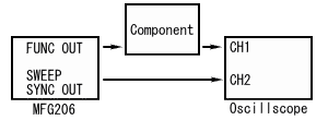
Measurement of frequency characteristics
¡@
(3) Application of the VCF function
(Frequency modulator)
Apply the signal and offset voltage to the VCF input. Any desired frequency
modulation effect can be obtained by setting the offset voltage to the carrier
frequency.
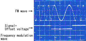 Frequency modulation wave
Arbitrary waveform generator
![]() Overall construction
Overall construction
The arbitrary waveform generator creates and edits a given waveform using the Windows 95 (the software to generate the arbitrary waveform and RS-232C cable are included as the standard accessories). The waveform is then transmitted to the MFG206 synthesizer. Any waveform can be easily formed and edited using the Windows 95. In addition, this function can also be used for a wide variety of applications with its high-capacity and high-resolution waveform data (128K words and l2 bits per word) since its sampling frequency is as high as 10MHz maximum.
¡@
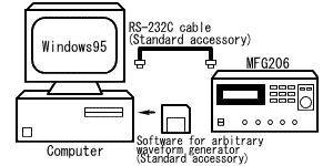
¡@
¡@
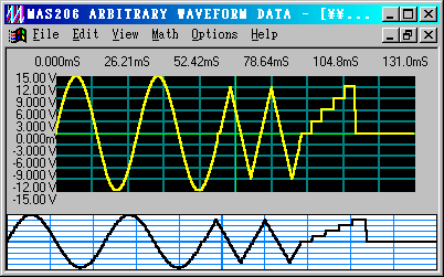
Windows 95 screen for forming waveform
¡@
![]() Forming of a waveform
Forming of a waveform
(1)
Standard waveform input
<Standard waveform>
Sine, triangle, square, ramp, sin X / X, (1-e-ax), e-ax, white noise, and DC.
There are nine standard waveforms available as stated above. It is also possible
to form a special waveform since the parameters can be precisely specified for
any one of the waveforms shown above.
| Parameter | Setting value | Subject waveform |
| Data number | 8 to 131072 | All of waveform |
| Amplitude | 0.001 to 1.00 | Waveforms excluding DC |
| Offset | -1.00 to +1.00 | All of waveforms |
| Cycle | 1.00 to 100.00 | Waveforms excluding white noise and DC |
| Phase (¢X) | 0.00 to 360.00 | Waveforms excluding white noise and DC |
| Duty ratio (%) | 0.00 to 100.00 | Square wave |
| Zero cross | 0 to 100 | sinX / X |
| Damp fact | -15 to +15 | (1-£`-ax) and £`-ax |
![]() Time can
be plotted on the horizontal axis in addition to the number of data. The voltage
can be plotted on the vertical axis in addition to the full scale.
Time can
be plotted on the horizontal axis in addition to the number of data. The voltage
can be plotted on the vertical axis in addition to the full scale.
|
|||||||||||||||||||||||||||||||||||||||
¡@
|
(2) Line input
¡@ ¡@ ¡@ ¡@ Formation of a waveform by straight lines ¡@ |
|
(3) Calculation input
Formation of waveform by adding or multiplying two waveform |
|
|
A value specified on the Y-axis can be clipped. |
|
|
A value specified on the Y-axis can be converted into an absolute value. |
|
|
Data can be switched vertically or horizontally (upside down or right-hand side to the left and left-hand side to the right). |
|
|
The waveform can be averaged (moving average). |
|
|
The data size can be changed, either on the X-axis or Y-axis or both. |
|
|
An offset can be added to the Y-axis. |
¡@
(4) One-point input
A given waveform can be created by inputting multiple points.
![]() Editing
of the waveform
Editing
of the waveform
| (1) Cut | A specified range is cut. |
| (2) Copy | A given waveform within the specified range is copied. |
| (3) Paste | A separately specified waveform is pasted. |
| (4) Undo | The operation that has just been made is cancelled. |
¡@
![]() File
File
| (1) New | A window to form a new waveform is opened. |
| (2) Open | File is opened. |
| (3) Close | File is closed. |
| (4) Save | The data contained in the waveform creation window is saved. |
| (5) Data import | The data in the ASCII format is read. |
| (6) Data export | The data in the ASCII format is output. |
| (7) Print | The waveform is printed out. |
| (8) Transmit | The waveform data is transmitted to the MFG206. |
Specifications
![]() Function synthesizer section
Function synthesizer section
| The following specification is guaranteed at 50% duty cycle and DC OFFSET : off. | |
| Waveform characteristics | |
| Kinds of waveforms | Sine, Triangle, Square wave and DC |
| Sine wave | |
| Distortion | less than 1% @ 1kHz |
| Triangle wave | |
| Lineality | more than 99% @ 10 to 90% of amplitude and 1mHz to 9.999kHz |
| Square wave | |
| Rise / Fall time | less than 16ns @ 10 to 90% of amplitude and 1kHz |
| Symmetry | less than 1% @ 1kHz |
| Overshoot | less than 5% |
| DC | |
| Output range | -15V to +15V @ open load |
| Setting resolution | sign + 3digits |
| Accuracy | less than (¡Ó5% of setting ¡Ó20mV) |
| Time characteristics | |
| Output frequency | |
| Frequency range | 1mHz to 20MHz (1mHz to 10MHz at triangle wave) |
| Setting resolution | 4digits |
| Accuracy | less than ¡Ó50ppm (0 to 40¢XC) |
| Duty ratio | This item is available for triangle and square waves |
| Setting range |
5 to 95 % / 1% step
(0.001Hz to 9.999kHz) |
| Accuracy |
less than ¡Ó1% (0.001Hz to
9.999kHz) |
| Output characteristics | |
| Output resistance | 50ohm ¡Ó5% |
| Amplitude | |
| Setting range | 300mVp-p to 30Vp-p @ open load |
| Setting resolution | 3digits |
| Accuracy | less than (¡Ó5% of setting ¡Ó10mV) @ 1kHz |
| Flatness |
less than ¡Ó3% (0.001 to
999.9Hz) |
| DC offset | |
| Output range | 0V ¡Ó15V @ open load and limited due to amplitude range |
| Setting resolution | sign +3digits |
| Accuracy | less than (¡Ó7% of setting ¡Ó20mV) |
| Output mode | |
| Continue | Continuous wave is output |
| Burst | |
| Frequency range | 0.100Hz to 999.9kHz |
| Frequency accuracy | less than (¡Ó10% of setting) |
| Burst rate | DC to 500kHz |
| Cycle number range | 1 to 4096 cycles |
| Phase range |
-90¢XC to +90¢XC / 1¢XC
step (0.100Hz to 9.999kHz) |
| Phase accuracy | less than ¡Ó3¢XC (0.100Hz to 1.000kHz) |
| Trigger source | External and Manual |
| Gate | |
| Frequency range | 0.100Hz to 999.9kHz |
| Frequency accuracy | less than (¡Ó10% of setting) |
| Gate rate | DC to 500kHz |
| Phase range |
-90¢XC to +90¢XC / 1¢XC
step (0.100Hz to 9.999kHz) |
| Phase accuracy | less than ¡Ó3¢XC (0.100Hz to 1.000kHz) |
| Trigger source | External |
| Sweep function | |
| Subject waveform | Sine wave |
| Sweep time axis | Linear and Logarithmic |
| Sweep time range | 0.01 to 10.0 sec / 0.01sec step |
| Sweep time accuracy | less than (¡Ó10% of setting) |
| Start freq. range | 100.0Hz to 20.00MHz |
| Start freq. accuracy |
less than (¡Ó5% of setting)
@ sweep range of 200kHz to 20MHz |
| Stop freq. range | 100.0Hz to 20.00MHz |
| Stop freq. accuracy |
less than (¡Ó5% of setting
¡Ó10 ¡Ñ (1+T) [kHz] ) |
|
Sweep range ¡@ |
4 ranges ( [200kHz to 20MHz], [10 kHz to1MHz], [1kHz to 100 kHz], [100Hz to 10 kHz] ) |
| Control input | |
| Trigger input | |
| Input resistance | 10kohm ¡Ó5% |
| Threshold level | TTL level |
| Min. pulse width | more than 25ns |
| Input damage level | ¡Ó20V (DC + ACpeak) max. |
| VCF input | |
| Input resistance | 10kohm ¡Ó5% |
| Frequency range |
6 ranges ( [200kHz to 20MHz], [10kHz to 1MHz], [1kHz to 100kHz], [100Hz to 10kHz], [10Hz to 1kHz], [1Hz to 100Hz] ) |
| Max. sweep width | approx. 1 : 100 @ 0.1 to 10V input |
|
Frequency accuracy |
less than (¡Ó10% of setting
¡Ó0.05K [Hz] ) (sine wave, K : maximum value of sweep range) |
| Input damage level | ¡Ó20V (DC + ACpeak) max. |
| Control output | |
| SYNC output | |
| Waveform | Square wave |
| Output level | TTL level |
| Rise/Fall time | less than 25ns |
| Output resistance | approx. 100ohm |
| Sweep SYNC output | |
| Waveform | Square wave |
| Output level | TTL level |
| Rise/Fall time | less than 25ns |
| Output resistance | approx. 100ohm |
| Arbitrary waveform generator section | |
| Waveform | |
| Waveform | |
| Horizontal axis | 8 to 131072 (128K) words |
| Vertical axis | 12 bits |
| Sampling frequency | |
| Setting range | 100Hz to 10MHz / 4digits setting |
| Accuracy | less than ¡Ó50ppm (0 to 40¢XC) |
| Forming of waveform | |
| Standard waveforms | Sine, Triangle, Square, Ramp, sinX / X, (1-£`-ax), £`-ax, White noise and DC |
| Straight line | Link two points by a line |
| Calculation | +, -, ¡Ñ, Clipping, Absolute, Mirror, Smoothing, Resize, Offset |
| One-point input | Input each point |
| Editing of waveform | Cut, Copy, Paste, Undo, Delete |
| File |
New, Open, Close, Save, Save as, Data import, Data export, Print, Printer setup, Transmit, Exit |
| Others | |
| Display system | |
| Monitor | LCD (20characters ¡Ñ 2columns) |
| Contents | Frequency, Amplitude, Waveform, Mode and other |
| Save of parameters | |
| Save number 10 | Interface |
| Interface | |
| Communication method | RS-232C (GP-IB is optional) |
| Baud rate | 2,400 to 57,600 |
| Commands | Writing and readout parameters, and writing of an arbitrary waveform |
| General | |
| Operating temperature | 0 to 40¢XC (Guaranteed at 23 ¡Ó 5¢XC) |
| Operating humidity | less than 40¢XC / 80%RH (Guaranteed at less than 28¢XC / 80%RH) |
| Storage temperature | -10 to +60¢XC / less than 80%RH |
| Warm-up time | more than 30min. |
| Power Supply | 90 to 130VAC / 180 to 250VAC (selected by a switch located on a rear panel) |
| Dimensions | 260 (W) ¡Ñ 115 (H) ¡Ñ 360 (D) mm (excluding projection) |
| Weight | approx. 4.1kg |
| Standard accessories | Instruction manual (1pc), Power cable
(1pc), Fuse (1pc), Floppy disk for arbitrary waveform generator (1pc), RS-232C cable (1pc) |
| Optional | |
| MFG206-GPIB (GP-IB board for MFG206 and factory option), | |
| GP-IB cable, BNC coaxial cable (1m) | |
Products list | brand | Model No. | Home