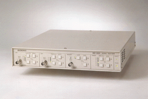
MS1220 1.2GHz Signal Digitizer
Three types of operations to support all applications digital oscilloscope / analog oscilloscope / built-in type digitizer

1MHz of Sampling Frequency Achieves (13 Time Faster Than Conventional Models)
The MS1220 adopts a sequential sampling system. Sampling frequency is known to determine the conversion time. This device has a sampling frequency of 1MHz that is about 13 times faster than that of conventional models. Since the conversion takes place within a very short time, a high-speed response is obtained. This is especially advantageous when the device is employed as a digitizer built in a user system. Moreover, its extremely wide measuring frequency band of 1.2GHz makes the device a valuable tool in evaluating and analyzing high-frequency analog circuits and ultra high-speed digital circuits.
Three Types of Operation That Support All Application
The
MS1220 comes equipped with three types of interfaces, so that it can adequately
respond to all kinds of intended applications. The interface connectors are
arranged on the back panel, as illustrated below :

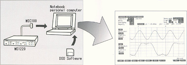
TYPE 1 : 1.2GHz Digital Oscilloscope
When you load the diskette (DOS software), supplied with the device, into your personal computer, the screen [1.2GHz Digital Oscilloscope] appears automatically.
¡@
<Setup>
Use the [COMPUTER I / F] connector. Set the mode (described further below)
to [DIGITAL]. You may use either a notebook-type or a desktop-type personal
computer. Especially, if you select a notebook-type personal computer, all you
have to do to use the device is to plug in the interface cable (MIC100) which is
supplied as an accessory. It is very easy to handle the device, and it requires
very little space.
¡@
<Operation
and Settings>
To operate the device and make the necessary setting, use the function keys of
the associated personal computer.
Features
(1)
Cursor Measurement
You will find this measurement method very handy when you need to read times or
voltages from waveforms displayed on the screen. The cursor moves step by step
when you operate a function key. However, the Shift key lets you move it 10
steps at a time, and the Ctrl key, 100 steps at a time.
¡@
![]() Time measurement (
¡µT
)
Time measurement (
¡µT
)
The
device measures the time between the O-cursor and the M-cursor. The number takes
a positive or negative sign depending on whether the M-cursor is located to the
right or the left of the O-cursor, respectively. Even when the M-cursor goes off
the screen as you enlarge the waveform image, measurement is performed
correctly.
![]() Voltage measurement (
¡µV )
Voltage measurement (
¡µV )
The device measures the differential voltage between the intersection of the O-cursor with the waveform and the intersection of the M-cursor with the waveform. The number takes a positive or negative sign depending on whether the M-cursor intersection is situated above or below the O-cursor intersection, respectively.
¡@
(2)
Averaging Process
The device performs simple averaging. This function proves quite effective in
extracting signals buried in noise. You can define the number of averaging times
at 2n(n=0 to 8, selected by 9 steps).
(3) Enlargement of Waveform
The time base can be expanded with the O-cursor in center. Six different
magnifications are available : ¡Ñ 1, ¡Ñ 2, ¡Ñ 4, ¡Ñ 8, ¡Ñ 16, and ¡Ñ 32. This
feature comes in handy when you need to observe a small part closely.
(4) Loading / Saving of Waveforms
A maximum of four waveforms can be saved. You will find this function convenient
when you have to compare the waveform currently displayed with those stored
inside.
(5) Printer Output
You can easily obtain a hard copy of the current screen by printing it out as
is.
¡@

TYPE2
: 1.2GHz Analog Oscilloscope
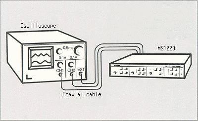
When simply coupled to an ordinary oscilloscope (enough
with a 20MHz band), the MS1220 functions as an [1.2GHz analog oscilloscope]
allowing high-speed waveforms to be observed.
<Setup>
Connect [CH1 SIG OUT], [CH2 SIG OUT], and [H-SYNC] to [CH1 INPUT], [CH2 INPUT],
and [EXT TRIG INPUT] of the associated oscilloscope using coaxial cables. Set
the mode (described further below) to [ANALOG]. Also, set the input sensitivity
of the oscilloscope to 0.1V / div, and the sweep time to 0.5ms / div.
¡@
 |
¡@
¡@
<Operations
and Settings>
You operate the MS1220 and make the necessary settings via switches that are
located on the front panel of this device. Numbers of VOLTS / FULL and TIME /
FULL reduced to 1 / 10 are displayed in VOLTS / DIV and TIME / DIV on the tube
screen of the oscilloscope. For example, if you have VOLTS / FULL : 50mV / Full
and TIME / FULL : 50ns / Full, the oscilloscope tube screen will indicate 5mV /
div and 5ns / div, respectively.
¡@

TYPE3 : Built-in Type 1.2GHz Digitizer
A
/ D-converted digital data are output as is at a high speed (max. 1µs /
data). A real-time [high-speed signal processing system] can be built up by
feeding these data into a user system, and then digitally processing the data.
Because remote operations and settings are possible on this type of device,
total control can be exerted on the device from the host side of the user
system.
<Setup>
Use the [DIGITAL I / O] connectors. Set the mode (described further below) to
[DIGITAL]. The device delivers the output data [CH1 (CH2) DATA0 to 7], as well
as [H-SYNC] and [DATA CLK], which are synchronized to the former, through said
connectors. The external system reels in the data according to [H-SYNC] and
[DATA CLK]. [DATA CLK] is a maximum of 1MHz.
 |
¡@
<Operations
and settings>
While the device can be operated and the necessary settings made through the
front panel of this device, the same operations and settings can also be
performed remotely from the outside, through the [DIGITAL I / O] connectors. If
you assign an address and set data corresponding to a set item, then apply a
negative [LATCH] pulse, the setting will take effect at its. For this reason,
you need to have the [REMOTE] terminal set in advance to Low level (remote
status) . The [START], [LATCH], and [REMOTE] terminals are pulled up with
10kohm.
<Operating
Sequence>
Upon receiving a [START] pulse, the device begins to capture waveforms, and
delivers A / D-converted data, one by one, in correspondence to the sampling
frequency. After the device completes the output, it waits for the next [START]
pulse to arrive. If another [START] pulse arrives within a waveform capturing
period, the device will restart.
¡@
 |
¡@
About the Mode
![]() ANALOG Mode :
ANALOG Mode :
While the one-sweep time (in low-speed sweep) remains constant at 5.12ms, the number of output dots changes with sampling period ¡µT
1-sweep time = 5.12ms (of which 5ms corresponds to TIME / FULL).
Number of output dots=5.12 (ms) ¡µT
¡@
![]() DIGITAL Mode :
DIGITAL Mode :
While the number of output dots remains constant at 1,024 dots, the one-sweep time changes with the sampling period.
One-sweep time = 1,024 ¡µT
Number of output dots = 1,024 (of while 1,000 dots correspond to TIME / FULL).
¡@
When making it operate on Windows
The following options are needed when operating MS1220 on Windows.
Optional
Interface
cable (for notebook PC).
Interface cable (for the ISA buses of a desktop PC).
Interface cable (for the PCI buses of a desktop PC).
¡@
In addition, the card / boards inserted in a host computer are as follows, and they should be prepared by a user.
![]() For notebook PC. DAQ Card-DIO-24
For notebook PC. DAQ Card-DIO-24
![]() For the ISA buses of desktop PC. PC-DIO-24PnP and
NI-DAQ
For the ISA buses of desktop PC. PC-DIO-24PnP and
NI-DAQ
![]() For the PCI buses of desktop PC. PCI-DIO-96 and
NI-DAQ
For the PCI buses of desktop PC. PCI-DIO-96 and
NI-DAQ
(ALL are the products provided from National Instruments Corporation.)
|
Specifications¡@ |
|||||||||||||||||||||||||||||||||||||||||
| When functioning as digital oscilloscope : | |||||||||||||||||||||||||||||||||||||||||
| Functions | |||||||||||||||||||||||||||||||||||||||||
| Cursor measurements | Time measurement( |
||||||||||||||||||||||||||||||||||||||||
| ¡@ | *Cursor moving steps : 1, 10, or 100 steps | ||||||||||||||||||||||||||||||||||||||||
| Averaging process | Simple averaging | ||||||||||||||||||||||||||||||||||||||||
| ¡@ | Number of averaging times 2n (n= 0 to 8) | ||||||||||||||||||||||||||||||||||||||||
| Waveform enlargement | ¡Ñ1, ¡Ñ2, ¡Ñ4, ¡Ñ8, ¡Ñ16, and ¡Ñ32 | ||||||||||||||||||||||||||||||||||||||||
| Waveform loading/saving | 4 waveforms (REF1 to REF4) | ||||||||||||||||||||||||||||||||||||||||
| Printer output | Output the screen display directly on a printer. | ||||||||||||||||||||||||||||||||||||||||
| Sweep | |||||||||||||||||||||||||||||||||||||||||
| Sweep mode | Continuous or single | ||||||||||||||||||||||||||||||||||||||||
| Interfaces | |||||||||||||||||||||||||||||||||||||||||
| Communication method | Port access method | ||||||||||||||||||||||||||||||||||||||||
| I/O addresses | 8bits ¡Ñ 5ports occupied | ||||||||||||||||||||||||||||||||||||||||
| Signal level | TTL level | ||||||||||||||||||||||||||||||||||||||||
| Connectors | 50-pin, half-pitch connector | ||||||||||||||||||||||||||||||||||||||||
| When functioning as a built-in digitizer : | |||||||||||||||||||||||||||||||||||||||||
| Input / output signals | |||||||||||||||||||||||||||||||||||||||||
| Output data | 8bits ¡Ñ 2channels | ||||||||||||||||||||||||||||||||||||||||
| Number of data | 1,024 dots / sweep | ||||||||||||||||||||||||||||||||||||||||
| Output synchronizing signal | H-SYNC and DATA CLK | ||||||||||||||||||||||||||||||||||||||||
| Input control signal | START, LATCH, and REMOTE | ||||||||||||||||||||||||||||||||||||||||
| *All three signal in negative logic (LATCH at the rise of negative pulse), | |||||||||||||||||||||||||||||||||||||||||
| pulled up to +5V with 10kohm. | |||||||||||||||||||||||||||||||||||||||||
| Negative pulse width of START and LATCH : 1µs or more. | |||||||||||||||||||||||||||||||||||||||||
| Input set value | Set data and addresses | ||||||||||||||||||||||||||||||||||||||||
|
|||||||||||||||||||||||||||||||||||||||||
| Signal level | TTL level | ||||||||||||||||||||||||||||||||||||||||
| Connector | 37-pin D-sub connector | ||||||||||||||||||||||||||||||||||||||||
| Operation | |||||||||||||||||||||||||||||||||||||||||
| Sequence | Single operation | ||||||||||||||||||||||||||||||||||||||||
| *performs one sweep upon receiving a START pulse from the outside. | |||||||||||||||||||||||||||||||||||||||||
| When functioning as an analog oscilloscope : | |||||||||||||||||||||||||||||||||||||||||
| CH1, CH2 SIG OUT | |||||||||||||||||||||||||||||||||||||||||
| Output voltage | 1V / Full (¡Ó 0.5V) | ||||||||||||||||||||||||||||||||||||||||
| Output resistance | Approx. 220ohm | ||||||||||||||||||||||||||||||||||||||||
| Sweep time | 5.12ms / sweep | ||||||||||||||||||||||||||||||||||||||||
| H-SYNC | |||||||||||||||||||||||||||||||||||||||||
| Output voltage | TTL level | ||||||||||||||||||||||||||||||||||||||||
| Logic | High level during sweep | ||||||||||||||||||||||||||||||||||||||||
| Common Specifications : | |||||||||||||||||||||||||||||||||||||||||
| Vertical system | |||||||||||||||||||||||||||||||||||||||||
| Number of input channels | 2channel, CH1 and CH2, operating simultaneously | ||||||||||||||||||||||||||||||||||||||||
| Input resistance | 50ohm | ||||||||||||||||||||||||||||||||||||||||
| Input sensitivity | 50mV to 1V / Full, 1-2-5steps, switched in 5steps | ||||||||||||||||||||||||||||||||||||||||
| Accuracy | ¡Ó 3% of Full Scale | ||||||||||||||||||||||||||||||||||||||||
| Offset range | ¡Ó 0.5V | ||||||||||||||||||||||||||||||||||||||||
| Dynamic range | 1Vp-p (¡Ó 0.5V) | ||||||||||||||||||||||||||||||||||||||||
| Frequency bandwidth | DC to 1.2GHz (-3dB) | ||||||||||||||||||||||||||||||||||||||||
| Rise time | 292ps or less | ||||||||||||||||||||||||||||||||||||||||
| Square-wave characteristic | Waveform distortion smaller than 7% | ||||||||||||||||||||||||||||||||||||||||
| VSWR | Less than 2.0 | ||||||||||||||||||||||||||||||||||||||||
| Channel isolation | 40dB or less | ||||||||||||||||||||||||||||||||||||||||
| Phase difference | 100ps or less | ||||||||||||||||||||||||||||||||||||||||
| Input damage level | ¡Ó3.5V (DC + AC peak) max | ||||||||||||||||||||||||||||||||||||||||
| Horizontal system | |||||||||||||||||||||||||||||||||||||||||
| High-speed sweep time | 10ns to 2µs / Full, 1-2-5 steps, switched by 8 steps | ||||||||||||||||||||||||||||||||||||||||
| Accuracy | ¡Ó 3% of Full Scale | ||||||||||||||||||||||||||||||||||||||||
| Mode | ANALOG / DIGITAL | ||||||||||||||||||||||||||||||||||||||||
| Low-speed sweep time | ANALOG mode : 5.12ms (of which 5ms corresponds to TIME / FULL). | ||||||||||||||||||||||||||||||||||||||||
| DIGITAL mode : 1,024• |
|||||||||||||||||||||||||||||||||||||||||
| Minimum delay time | 60ns or less 10ns / Full | ||||||||||||||||||||||||||||||||||||||||
| Sweep delay time | Approx. (High-speed sweep time) ¡Ñ 1 | ||||||||||||||||||||||||||||||||||||||||
| Number of output dots | ANALOG mode : 5.12 (ms) / |
||||||||||||||||||||||||||||||||||||||||
| DIGITAL mode : 1,024dots | |||||||||||||||||||||||||||||||||||||||||
| Trigger system | |||||||||||||||||||||||||||||||||||||||||
| Signal source | External | ||||||||||||||||||||||||||||||||||||||||
| Trigger system | NORM | ||||||||||||||||||||||||||||||||||||||||
| Trigger resistance | 50ohm | ||||||||||||||||||||||||||||||||||||||||
| Input coupling | AC | ||||||||||||||||||||||||||||||||||||||||
| Polarity | Rise, fall | ||||||||||||||||||||||||||||||||||||||||
| Frequency range | 5kHz to 200MHz | ||||||||||||||||||||||||||||||||||||||||
| Sensitivity | 200mV or more (10kHz to 100MHz) | ||||||||||||||||||||||||||||||||||||||||
| Trigger level range | ¡Ó 1.5V | ||||||||||||||||||||||||||||||||||||||||
| Sampling frequency | Max. 1MHz | ||||||||||||||||||||||||||||||||||||||||
| Input damage level | 7Vp-p (AC) ¡Ó 20V (DC) | ||||||||||||||||||||||||||||||||||||||||
| A / D conversion part | |||||||||||||||||||||||||||||||||||||||||
| A / D converter | 8bits ¡Ñ 2channels | ||||||||||||||||||||||||||||||||||||||||
| Sampling speed | Equal to the sampling frequency | ||||||||||||||||||||||||||||||||||||||||
| General | |||||||||||||||||||||||||||||||||||||||||
| Operating temperature | 0 to 40¢XC (Guaranteed at 23 ¡Ó 10¢XC) | ||||||||||||||||||||||||||||||||||||||||
| Operating humidity | Less than 40¢XC / 90%RH (Guaranteed at less than 33¢XC / 80%RH) | ||||||||||||||||||||||||||||||||||||||||
| Storage temperature | -10¢XC to 60¢XC, less than 60¢XC / 80%RH | ||||||||||||||||||||||||||||||||||||||||
| Power supply | 90 to 127V AC | ||||||||||||||||||||||||||||||||||||||||
| Power consumption | Approx. 20VA | ||||||||||||||||||||||||||||||||||||||||
| Dimensions | 320 (W) ¡Ñ 56 (H) ¡Ñ 350 (D) mm | ||||||||||||||||||||||||||||||||||||||||
| Weight | Approx. 2.5kg | ||||||||||||||||||||||||||||||||||||||||
| Accessories : | |||||||||||||||||||||||||||||||||||||||||
| MIC 100 interface cable (for notebook-type personal computer) (1pc) | |||||||||||||||||||||||||||||||||||||||||
| DSO software (1pc) | |||||||||||||||||||||||||||||||||||||||||
| Instruction manual (1pc) | |||||||||||||||||||||||||||||||||||||||||
| Power cord (1pc) | |||||||||||||||||||||||||||||||||||||||||
| Fuse (1pc) | |||||||||||||||||||||||||||||||||||||||||
| Options : | |||||||||||||||||||||||||||||||||||||||||
| MIC 101 interface cable (for desktop-type personal computer) | |||||||||||||||||||||||||||||||||||||||||
| MIB 100 interface board (for desktop-type personal computer) | |||||||||||||||||||||||||||||||||||||||||
| BNC coaxial cable (1m) | |||||||||||||||||||||||||||||||||||||||||
|
|
|||||||||||||||||||||||||||||||||||||||||
Products list | brand | Model No. | Home