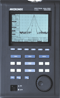
MSA338 3 .3GHz Handheld Spectrum Analyzer

MSA338 is an authentic spectrum analyzer providing performance and functions that are comparable to large-size bench type in a compact, lightweight and inexpensive model.
Features
1. Compact and lightweight 1.7kg
The dimensions are as small as 162 (W) ¡Ñ 70 (H) ¡Ñ 260 (D) mm, and the weight is only 1.7 kg including the battery. It is very convenient for outdoor use and while on business trips.
¡@
2. Measuring frequency range 50kHz to 3.3GHz
The dimensions are as small as 162 (W) ¡Ñ 70 (H) ¡Ñ 260 (D) mm, and the weight is only 1.7 kg including the battery. It is very convenient for outdoor use and while on business trips.
¡@
3.Operation with battery for 100 minutes
When the battery MB300 (optional) is fully charged, MSA338 operates for about 100 minutes (with the back light turned off). It is extremely convenient for outdoor use and for measuring wireless LAN installation environment.
¡@
4. Performance that is comparable to large-size bench type
MSA338 guarantees a highly stable frequency axis by PLL synthesizer system. The center frequency setting resolution is 100kHz. Furthermore, the average noise level of -110dBm (typical) provides a wide dynamic range and the reference level can be set in 1 dB step.
¡@
| 5. Abundant functions | |
|
|
| * Channel power measurement | * MAX HOLD |
| * Adjacent channel power measurement | * MIN HOLD |
| * Occupied bandwidth measurement | * AVERAGE |
| * Electric field strength measurement | * OVER WRITE |
| * Magnetic field strength measurement | |
|
|
|
|
|
|
| * Electric field strength meas. ¡P¡P¡P Optimum for measurement of cellular phone and wireless LAN working environment. | |
| * Magnetic field strength meas. ¡P¡P¡P Optimum for EMI design of PCBs and for evaluation of signal quality. | |
¡@
6. Auto tuning
The center frequency is set at the spectrum of the maximum level in the 3.3GHz band, and in addition, optimum reference level, resolution bandwidth, video bandwidth and sweep time are set when the AUTO TUNE key is pressed. This function is very convenient for measurement of an unknown signal.
¡@
7. Auto range operation
The resolution bandwidth, video bandwidth and sweep time are automatically set based on the frequency span. It is also possible to set auto range operation only one or two out of resolution bandwidth, video bandwidth and sweep time.
¡@
8. Hard copy of the image
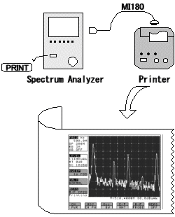
Connect a printer (optional) and press the PRINT key on MSA338. The image on the screen is printed as it is.
¡@
9. High resolution display on the PC screen
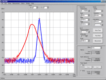
The spectrum waveform is displayed at high resolution, 1000 points in the horizontal axis, on the PC screen when "PC Software MAS300" (optional) is used.
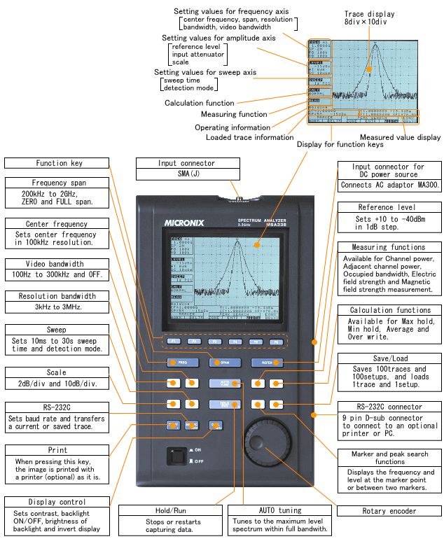
Operational explanation
¡@
¡@
 |
¡@
Measuring functions
![]() Channel power measurement
Channel power measurement
Measures the sum of the power in the zone specified by the zone center and zone width (slash area in figure). In short, it is possible to measure the total power in the specified frequency band. Of course it is possible to measure the noise power.

¡@
![]() Adjacent
channel power measurement
Adjacent
channel power measurement
Capable of measuring the adjacent channel power leakage as the ratio of the power in the range specified by offset frequency and bandwidth (slash area in figure) to the carrier wave power. Both the upper and lower side power leakage are measured.
Furthermore, the method for measurement may be selected out of three methods, i.e., total power method, reference level method and in-band method, from the classification of definition of carrier wave power.
¡@
¡@
¡@
![]() Magnetic
field strength measurement
Magnetic
field strength measurement
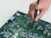
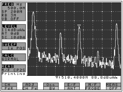
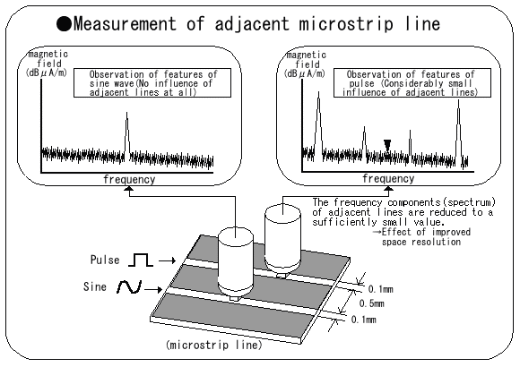
MSA338 is capable of precisely measuring the magnetic field distribution on an LSI or a printed circuit board using magnetic field probe CP-2S (optional).
¡@
As the magnetic field detection portion of CP-2S is of a shielded loop structure that adopts glass ceramic multi-layer board technology of excellent high frequency characteristics, it is possible to take measurement at high reproducibility by detecting magnetic field components only. The measuring frequency range is as broad as 10MHz to 3GHz, and the measured value is calibrated in the instrument.
Evaluation of effectiveness of the bypass capacitor located at the power supply terminal of an LSI and evaluation of wiring rule on a printed circuit board can be raised as typical use of CP-2S. CP-2S is not affected by adjacent patterns because of high space resolution.
¡@
¡@
![]() Occupied bandwidth measurement
Occupied bandwidth measurement
It is possible to measure the occupied frequency bandwidth as the bandwidth of the point that is lower by X (dB) than the peak level or as the bandwidth of the point of Y (%) of the total power.

¡@
![]() Electric
field strength measurement
Electric
field strength measurement
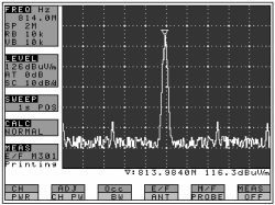
It is possible to measure the electric field strength by connecting a dipole antenna (optional) to the input connector. A dipole antenna that suits the use is available. M301 is mainly for PDC 800MHz and GSM 900MHz band, M302 is mainly for PDC 1500MHz band, M303 is mainly for PHS, W-CDMA and GSM 1800 / 1900MHz band, and M304 is mainly for 2.4GHz wireless LAN and Bluetooth. M304 is capable of measuring direct sequence spread spectrum, frequency hopping and Bluetooth system by 10 ms sweep time and MAX HOLD function.
¡@
The conventional method covering low frequency through high frequency with a single antenna results in low antenna gain because of using a range deviating from the antenna resonance point, and the dynamic range largely worsens as a result.
MSA338, however,
provides an antenna for each frequency band and uses a
resonance point of high gain only, and accordingly, it is
capable of securing a wide dynamic range. Antennas of other
bands will be also prepared if requested.
As the electric field strength is calibrated for each antenna
in MSA338, it is possible to directly read the measured value.

¡@
Calculation functions
Max hold¡@
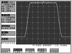
The update spectrum data is compared with that of last time for each point of the X-axis, and the larger one is retained and displayed. The number of times of sweep can be set in the range from 2 to 1024 times by steps, which is a power of 2, or by infinite. It is possible to observe burst signal and frequency drift.
¡@
¡@
Min hold
The update spectrum data is compared with that of last time for each point of the X-axis, and the smaller one is retained and displayed. The number of times of sweep can be set in the range from 2 to 1024 times by steps, which is a power of 2, or by infinite.
¡@
¡@
Average
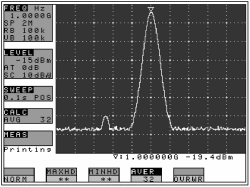
Simple averaging processing is executed at each sweep. The number of times of averaging can be set from a range of 2 to 256 times by steps, which is a power of 2. The signal components buried in the noise can be measured.
¡@
¡@
Over write
The image on the screen is not cleared for each sweep, and overwriting display is executed. It is, therefore, possible to observe the process of changes in the signal.
Marker and peak search
Marker measurement
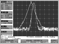
Two different modes are available for marker measurement. One is normal marker mode to measure and display the frequency (maximum effective number of digits : 7) and level (maximum effective number of digits : 3) of the marker point, and another is delta marker mode to measure and display the frequency difference and level difference between two markers (one of which is a reference marker).
|
Normal marker measurement |
Delta marker measurement |
¡@
¡@
Peak search
Two different modes are available for peak search. One is normal peak search mode to search for the peak level with all of 10div of the frequency axis as the search range, and another is in-zone peak search mode to search for the peak level in the range specified by the center value and width. NEXT search (search for the next smaller level) of up to 9 is permitted in the normal peak search mode. The marker moves to the peak level at each sweep in the in-zone peak search mode.
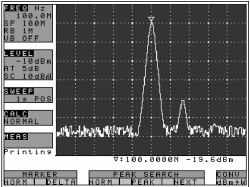
Normal peak search |
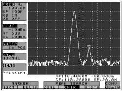
Zone peak search |
¡@
AUTO tuning
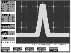
The search for the signal of the maximum level in the 3.3GHz band is executed and the result is displayed in the specified frequency span when the AUTO TUNE key is pressed. The spectrum is tuned to the vicinity of the center of the screen, and the reference level, resolution bandwidth, video bandwidth and sweep time are automatically set at optimum values. This function is very convenient when used for measurement of an unknown signal.
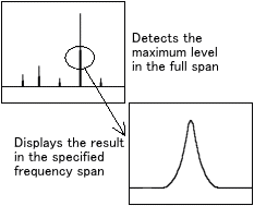
Auto range
Resolution bandwidth, video bandwidth and sweep time are set automatically based on the specified frequency span. Furthermore, it is also possible to automatically set one or two of either resolution bandwidth, video bandwidth and sweep time. The operator is released from troublesome operation because these three parameters that accompany the frequency span are set automatically.
Save/Load
It is possible to save 100 traces and 100 setups. The load is one trace and one setup. This function may be used when various data are acquired and they are evaluated later, or when it is wanted to make a comparison with formerly acquired data. The saved traces and setups can be transferred to a PC through RS-232C.
Hard copy of display
Hard copies of the image on the screen can be produced if a printer (optional) is connected, using RS-232C cable MI180 (optional), to the RS-232C connector of this instrument. Printing begins when the PRINT key is pressed. The printer is of dual power supply scheme, i.e., AC adaptor and battery, and it is possible to easily produce hard copies of measured data even outdoors where no AC power supply is available. The operating time of the battery-powered printer is about 30 minutes (when used continuously), and it is possible to produce about 80 hard copies of images on the screen.
¡@
High resolution display on the PC screen
Although the spectrum is displayed by 250 points on the horizontal axis on the spectrum analyzer screen, it is fetched by 1000 points per sweep in the instrument. When "PC Software MAS300" (optional) is used, all of these 1000 points are transferred to a PC (the maximum transfer rate is 38,400 bps) and are displayed on the PC screen. The image, therefore, becomes clearer. Furthermore, setup of spectrum analyzer can be made from the PC side.
Standard accessories and optional accessories
¡@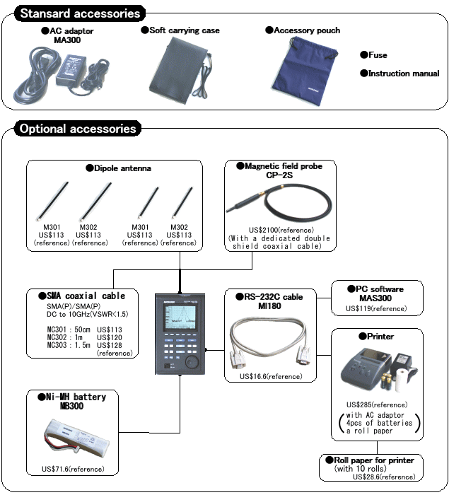
Standard accessories and optional accessories
¡@
Magnetic field probe
| Items | Specifications |
| Frequency range | 10MHz to 3GHz |
| Space resolution | approx. 0.25mm (depending on objects) |
| Dimensions |
outside : 12Ø x 135mm probe tip : 2mm (W) ¡Ñ 1mm (T) |
| Connector | SMA (P) |
¡@
Printer
| Items | Specifications |
| Printing method | Thermal serial dot method |
| Paper | 80mm width thermal paper |
| Power source |
internal : alkaline battery
(4pcs) external : DC6V / 1.5A |
| Dimensions | 134 (W) ¡Ñ 58 (H) ¡Ñ 180 (D) mm |
| Weight | approx. 550g (mainframe only) |
¡@
Dipole antenna (Antenna gain and VSWR are specified at a center of frequency range)
| Items | M301 | M302 | M303 | M304 |
| Frequency range | 0.8 to 1GHz | 1.25 to 1.65GHz | 1.7 to 2.2GHz | 2.2 to 2.65GHz |
| Antenna gain | >1dBi | >1dBi | >1dBi | >1dBi |
| VSWR | <1.5 | <1.5 | <1.5 | <1.5 |
| Dimensions | 7.5Ø ¡Ñ 250mm | 7.5Ø ¡Ñ 250mm | 7.5Ø ¡Ñ 180mm | 7.5Ø ¡Ñ 180mm |
| Weight | approx. 20g | approx. 20g | approx. 15g | approx. 15g |
Specifications
| Frequency section | |||||||||
| Frequency range | 50kHz to 3.3GHz | ||||||||
| Center frequency | |||||||||
| Setting resolution |
100kHz |
||||||||
| Accuracy |
|
||||||||
| RBW frequency error |
within ¡Ó6% of RBW (RBW : 3kHz, 30kHz) |
||||||||
| Frequency span | |||||||||
| Setting range | 0Hz (zero span), 200kHz to 2GHz (1-2-5step) and 3.3GHz (full span) | ||||||||
| Accuracy | within ¡Ó3% ¡Ó20TkHz ¡Ó1dot (Frequency
span : 200kHz to 10MHz, 23 ¡Ó5¢XC) within ¡Ó3% ¡Ó200TkHz ¡Ó1dot (Frequency span : 20MHz to 3.3GHz, 23 ¡Ó5¢XC)
|
||||||||
| Display resolution |
Frequency span/250 |
||||||||
| Display dot number | 251dots, 1001dots (only the measurement
by RS-232C communication)
|
||||||||
| Resolution bandwidth | 3dB bandwidth | ||||||||
| Setting range | 3kHz to 3MHz (1-3step) and AUTO | ||||||||
| Accuracy | within ¡Ó20% | ||||||||
| Selectivity | 1 : 12 (typical, 3dB : 60dB) | ||||||||
| Video bandwidth | 100Hz to 300Hz (1-3step), OFF and AUTO | ||||||||
| SSB Phase noise | -90dBc / Hz (typical, 100kHz offset,
RBW : 3kHz, VBW : 100Hz, Sweep time : 0.3s) |
||||||||
| Spurious response | less than -60dBc | ||||||||
| Harmonics | less than -40dBc (50kHz to100MHz) less than -45dBc (100MHz to 3.3GHz) |
||||||||
|
|
|||
| Amplitude section | |||
| Reference level | |||
| Setting range | +10 to -40dBm (1dB step) | ||
| Accuracy |
within ¡Ó0.8dB ¡Ó1dot |
||
| Unit | dBm, dBV, dBmV, dBµV, dBµV/m,
dBµA/m
|
||
| Average noise level | -110dBm (typical, center frequency : 100MHz RBW : 3kHz, VBW : 100Hz) | ||
| Frequency Characteristic |
within ¡Ó2.0dB ¡Ó1dot (50kHz to100MHz) |
||
| Input impedance | 50ohm | ||
| Input VSWR | less than 2.0 | ||
| Input attenuator | |||
| Operating range | 0 to 25dB (1dB step), coupled with reference level | ||
| Switching error | within ¡Ó0.6dB | ||
| RBW switching error | within ¡Ó0.6dB | ||
| Display resolution | 0.4dB (10dB/div), 0.08(2dB/div) | ||
| Display dot number | 200dot | ||
| Display scale | |||
| Scale | 10dB / div, 2dB / div | ||
| Accuracy | within ¡Ó0.2dB / 2dB ¡Ó1dot within ¡Ó0.8dB / 10dB ¡Ó1dot within ¡Ó1.6dB / 70dB ¡Ó1dot |
||
| Input damage level | +20dBm (CW average power), 25VDC | ||
| Input connector | SMA (J) | ||
|
|
|||
| Sweep section | |||
| Sweep time | |||
| Setting range |
10ms to 30s (1-3step, frequency span :
0 to 2GHz) and AUTO |
||
| Accuracy |
within ¡Ó0.1% ¡Ó1dot ( frequency span :
0 to 2GHz) |
||
| Trigger mode | AUTO (frequency span : zero span) | ||
| Detection mode | Positive peak, Negative peak, Sample
|
||
|
|
|||||
| Functions | |||||
| Marker |
|
||||
| Peak search |
|
||||
| Calculation |
NORM, MAX HOLD, MIN HOLD, AVERAGE, OVER
WRITE |
||||
| Measuring |
Channel power, Adjacent channel power, Occupied frequency bandwidth, Electric field strength (needs optional antenna), Magnetic field strength (needs optional magnetic field probe) measurement. |
||||
| AUTO tuning |
When pressing AUTO TUNE key, the maximum level spectrum within 3.3GHz bandwidth is adjusted to center, and reference level, RBW, VBW and sweep time are adjusted to optimum values. |
||||
| Save / Load | |||||
| Save | Saves 100 traces and 100 setups | ||||
| Load | Loads 1 trace and 1 setup | ||||
|
|
|
| General | |
| Communication | |
| Interface | RS-232C |
| Baud rate | 2,400 to 38,400bps |
| Hard copy | Allows direct hard copy with an optional printer |
| Display | |
| Display | LCD |
| Backlight | CFL backlight |
| Resolution | 320 (H) ¡Ñ 240 (V) dots |
| Power source | |
| Battery | Ni-MH Battery (optional) |
| External DC source | Pin jack, DC5V / 4A |
|
|
|
| Other | |
| Operating temperature | 0 to 40¢XC (Guaranteed at 23 ¡Ó10¢XC, without soft carrying case) |
| Operating humidity |
less than 40¢XC / 80%RH (Guaranteed at
less than 33¢XC / 70%RH, |
| Storage temperature | -20 to 60¢XC, less than 60¢XC / 70%RH |
| Dimensions | 162 (W) ¡Ñ 70 (H) ¡Ñ 260 (D) mm (exclude projections and stand) |
| Weight | approx. 1.7kg (included battery), approx. 1.5kg(without battery) |
|
|
| * MICRONIX Corporation reserves the right to make changes in design, specification and other information without prior notice. |
Spectrum Analyzer Compare List | Home
¡@