|
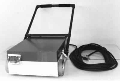
Measurement Cart |
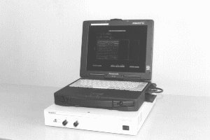
PC and communication box |
 |
 |
Road survey radar
|
Measurement Cart |
PC and communication box |
 |
 |
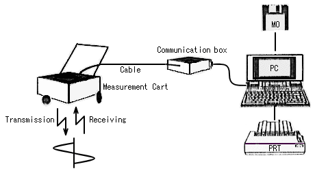
Surveys holes under the road and other objects
underground.
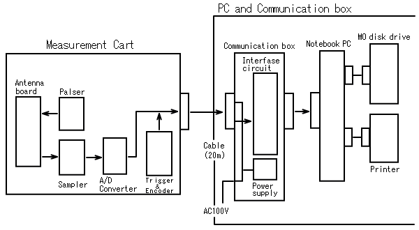
System block
System block diagram
¡@
Measurement equipment
Output waveform of PC
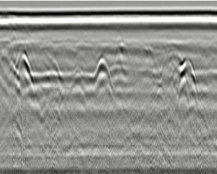
On PC screen, the sectional image obtained by
road survey radar is as shown below. Waveforms of various kinds by
surveying objects underground etc. are displayed. Basing on these
images, experts make judgment.
¡@
| Specifications | |
| Transmission section | |
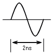
| Transmission waveform | Mono-cycle wave
|
|
Transmission frequency |
500MHz |
| Antenna | Flat antenna (bow tie antenna) |
| Receiving section | |
| Antenna | Flat antenna (bow tie antenna) |
| A / D converter | 8bits |
| Depth direction | 256 points |
| Sweep width | 2 range of 40ns and 60ns |
| Delay | 0 to 20% of sweep width |
| Variable by half-fixed volume. | |
| Communication section | |
| Communication system | 8bits parallel transmission |
| Communication speed | Based on "measurement speed" |
| Cable length | 20m |
| PC section | |
| Object PC | DOS / V notebook PC |
| Printer output | Output B scope |
| Picture display | 16 gradation gray scale display |
| Memory medium for data processing | Hard disk |
| Memory medium for data store | MO disk |
| Surveying capability | |
| Maximum surveying depth | 1.5m (asphalt pavement ideal state) |
| Maximum measurement speed | 5km / h |
| Others | |
| Composition | Measurement Cart (made from aluminum) |
| Communication box | |
| Cable between cart and communication box (20m) | |
| Notebook PC (with HD) | |
| Printer | |
| Power supply | MO drive |
| AC100V | |
|
|
|