Shielding Room
A shielded enclosure for every RF requirement
- Modular Construction
- Space Saving
- Demountable
- Guarantee
- Flexible
- Cost Saving
- Custom Designed
RF Shielded Enclosures
The performance of electromagnetic equipment depends largely on the effectiveness of RF shielded enclosures, as the use of any sensitive equipment in an open area is limited by undesired RF interferences. A RF interference free area can only be obtained by use of a shielded enclosure in which is placed either the equipment producing the interference or the equipment affected by the interference.
MIKO can provide a shielded enclosure of any size, from the smallest prefabricated unit for production - R&D Lab. to the largest and most complex custom-built installation for a computer or communication centre, according to your requirements.
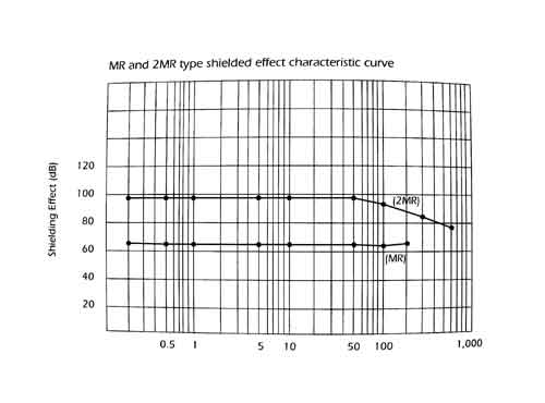
MR-K, 2MR-K, SR-K and 2SR-K are steel single or double shielded rooms. All materials are electroplated with Zinc for protecting them against corrosion damage. Double shielded 2SR-K can gain more 20dB shielding effect over that of singled shielded SR-K in all frequency range.
Shielding Room
MR-K, SR-K: Steel panel single shielded room
2MR-K, 2SR-K: Steel panel double shielded room

| Type | Dimension (mm) | ||
|---|---|---|---|
| Width | Depth | Height | |
| MR-1K | 1,220 | 1,220 | 2,050 |
| 2MR-1K | 1,220 | 1,220 | 2,050 |
| SR-05K | 1,824 | 1,220 | 2,050 |
| SR-1K | 1,824 | 1,824 | 2,050 |
| SR-2K | 2,724 | 1,824 | 2,050 |
| SR-3K | 2,724 | 2,724 | 2,050 |
| 2SR-1K | 1,824 | 1,824 | 2,050 |
| 2SR-2K | 2,724 | 1,824 | 2,050 |
| 2SR-3K | 2,724 | 2,724 | 2,050 |
Precaution before Installation
Terminals
Since all FILTER are symmetrical π-type low pass filters, the input/output terminals are not differentiated. Therefore, it makes no difference which terminal is used as the input terminal.
Shielding
Shielding of equipment
The FILTER suppresses interference transmitted through the power line, but cannot suppress interference signals radiated directly into space. Consequently, when desiring to suppress such interference, the equipment must be shielded (refer to Figure 1).
Shielding between input and output terminals
When the input and output terminals are not shielded even though the equipment is shielded, interference signals will leak in. Therefore, shielding between the input and output terminals is necessary (refer to Figure 2). Since the frequency supression range of the FILTER is comparatively low and the radiated interference is small, shielding is generally uncessary.
Installation Details
Installation
The FILTER may be installed either inside or outside the shielding.
Since interfering signals are made to flow to the shielding through the FILTER case, connection of the FILTER case and shielding should be made considering the following points in order to make the contact impedance as small as possible.
- Remove all paint, rust, oil or other materials which might hinder electrical connection at the FILTER installation position.
- Do not connect the FILTER case to the shielding with lead wires. Always secure the FILTER case directly to the shielding.
Grounding
Capacitors are inserted between the line and shielding as shown in Figure 37 when the FILTER is installed, and a difference of potential is produced between the ground and shielding. Consequently there is the danger of electric shock if the shielding is touched. Therefore, the shielding must be securely grounded (see Figure 38).