edance Analyzer
ZA57630
"True Value"
Measuring true characteristics.
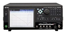
▲ ZA57630
![]()
For a broad range of impedance measurement requirements, from electronic parts and semi-conductor devices to material and substance characteristics assessments.
Measurement signal amplitude| Basic accuracy | ±0.08% |
| Measurement frequency | 10 µHz to 36 MHz |
| Measurement Impedance range | 10 µΩ to 100 GΩ (Mode: IMPD-EXT) |
| Measurement signal amplitude | 0.01 mVrms to 3 Vrms 0.1 µArms to 60 mArms |
| DC bias | −5 V to +5 V/−40 V to +40 V (more than
1 kHz) 100 mA to +100 mA |
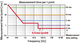
| Measurement time | 0.5 ms/point |
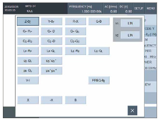
| Measurement parameter | Z, R, X, Y, G, B, Ls, Lp,
Cs, Cp, Rs, Rp, θz, θy, D, Dε, Dµ, Q, V, I, εs, εs’, εs”, µs, µs’, µs”, FREQUENCY |
High speed measurement Industry fastest 0.5 ms/point
The fastest in the industry at 0.5 ms/point. Reduce takt time. In addition, by increasing the measurement time to be set, the measurement results are averaged and the influence of noise is reduced. The optimum measurement time can be selected as required.
Four measurement modes Able to handle a broad range of DUTs
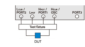
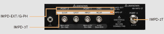
IMPD-3T
Default measurement mode
This mode provides high-accuracy measurements across a broad range of frequencies. Test leads and test fixtures can be used to suit test materials with a variety of different shapes.
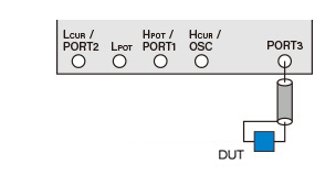
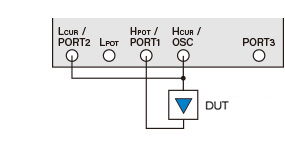
IMPD-2T
High-frequency measurement mode
This mode allows more stable measurements at high-frequency of 10 MHz or more. 2-terminal measurements using N connectors allows stable measurements even when using long cables.
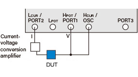
IMPD-EXT
Expanded measurement mode
Allows external amplifiers, shunt resistors or other devices to be connected. Allows measurements outside of the unit's specifications, like applying high voltages or detecting small voltages/currents.
G-PH
Gain/phase measurement mode
This mode provides measurements of transmission characteristics of devices like filters and amplifiers. Accurately measures the frequency response (gain, phase) when applying a sweep signal to the measured circuit.
Front panel Measurement connectors
Features
A diverse array of functions to suit any
application!
Highly repeatable and accurate measurements.
Accurate
assessments conducted under actual usage conditions.
Electronic
parts and materials may indicate varying characteristics at different
measurement frequencies or when different signal levels are applied. To assess
true characteristics, it is important to take measurements under actual
operating conditions by sweeping the frequency, AC amplitude and DC bias.
Features
| ● SEQUENCE MEASUREMENT FUNCTION |
| ● SWEEP |
| ● SETTING MEASUREMENT AND OTHER CONDITIONS |
| ● MEASUREMENT RANGE |
| ● MEASUREMENT DELAY FUNCTION |
| ● AUTOMATIC HIGH DENSITY SWEEP |
| ● ERROR CORRECTION FUNCTION |
| ● MARKER CONTROL |
| ● GRAPH DISPLAY |
Useful Function
| ● RESONANT FREQUENCY TRACKING FUNCTION |
| ● EQUIVALENT CIRCUIT ESTIMATION FUNCTION |
| ● PIEZOELECTRIC CONSTANT CALCULATION FUNCTION |
| ● RELATIVE PERMITTIVITY MEASUREMENT |
| ● RELATIVE MAGNETIC PERMEABILITY MEASUREMENT |
| ● COMPARATOR/HANDLER INTERFACE |
| ● EXTERNAL REFERENCE CLOCK |
| ● MEMORY CONTROL |
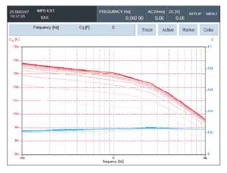
SWEEP Frequency, AC amplitude, DC bias, zero span
AC amplitude sweep
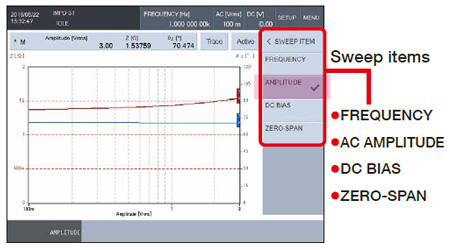
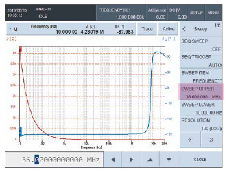
Frequency sweep
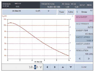
DC bias sweep
Zero span
Takes measurements under fixed conditions without changing frequency, AC amplitude or DC bias parameters, to observe the change in characteristics over time (horizontal axis: time)
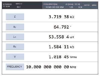
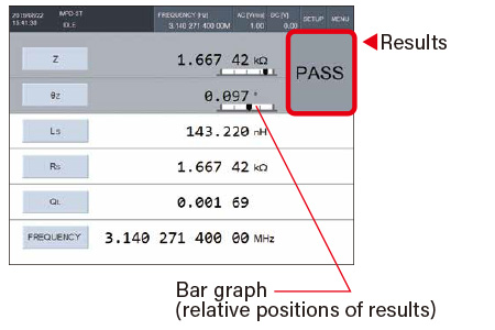
● Also capable of spot measurements
Measures a fixed frequency, AC amplitude and DC bias, and displays the results as numerical values. Up to 6 items can be configured.
For
measurements on production lines
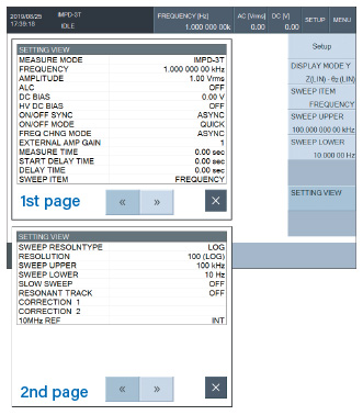
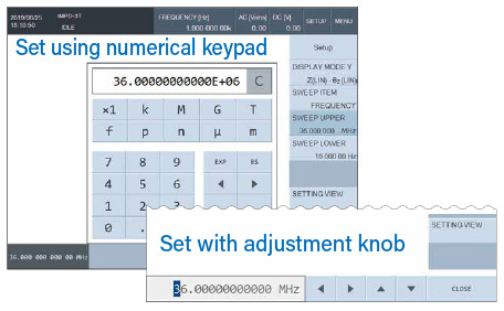
SETTING MEASUREMENT AND OTHER CONDITIONS
Settings intuitively on a single screen
Setting items (SETTING VIEW)
Graph axis setting
Frequency settings
MEASUREMENT RANGE
Auto range
Takes measurements by setting the optimal measurement range automatically while monitoring measurement results. This is effective when there are significant changes in measurement data.
Fixed range
The measurement range is fixed, which prevents discontinuity (steps) in the measured value caused by changes in the range.
MEASUREMENT DELAY FUNCTION
If
sweep parameters such as frequency or AC amplitude are changed while sweep is
in progress, incorrect measurement results can be generated due to transient
response.
The time until measurements start after parameters are changed can be delayed.
Two delay types are available: “Measurement start delay” and “Measurement
delay”
AUTOMATIC HIGH DENSITY SWEEP
This
function automatically raises the frequency density only for sections where the
measurement data changes suddenly during frequency sweep measurements.
During resonance characteristic measurements of devices like piezoelectric
vibrators and crystal oscillators, this function is useful.
ERROR CORRECTION FUNCTION
Corrections to causes of measurement errors, for accurate assessments.
To conduct accurate measurements, various measurement error causes such as residual impedance and cable length must be corrected properly.
Open correction
Reduces errors caused by residual admittance
Short correction
Reduces errors caused by residual impedance
Load correction
Corrects deviations from true values using samples with known values as standard impedance
Port extension
Corrects phase errors due to transmission delay time when using long cables
Slope compensation
Removes the effect of potential fluctuation wave included in the measurement signal. Effective for measurements of samples such as batteries with potential changes due to charging and discharging
Equalizing
Measures the frequency characteristics of sensors, cables and other externally connected measurement devices, and corrects the amount of error of those measurement devices
Input weighting
Corrects the probe attenuation or pre-amp gain
Self-calibration
Self-calibrates errors
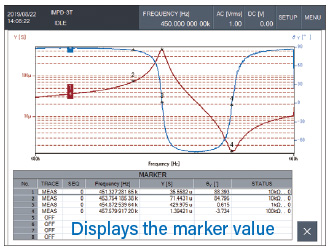
MARKER CONTROL
Reads
the measurement values for X, Y1 and Y2 shown on the graph.
Up to 8 markers can be used.
Δ Marker
Displays the difference from the standard marker (Marker 1)
ΔTRKG Marker
Displays the difference in the same way as the difference marker. When marker 1 is moved, it moves while keeping the difference in the sweep value constant.
Marker search function
Automatically searches points that match the setting conditions
SEQUENCE MEASUREMENT FUNCTION
Multiple
measurement conditions are set in advance, and this function conducts
measurements in order under those conditions.
The sweep range can be split into segments, with measurements taken under
different conditions for each segment range.
Enables efficient measurements of multilayer ceramic capacitors (MLCC), and other devices with characteristics that vary
with voltage.
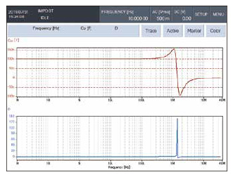
GRAPH DISPLAY
SINGLE/SPLIT display
Select from “SINGLE” with one graph shown per screen, or “SPLIT” with two graphs shown top and bottom
Phase display control
±180°, 0° to +360°, −360° to 0°, UNWRAP (continuous display), 360° shift, aperture (group delay characteristics)
Trace control
Allows overwriting of measurement data trace (MEAS) and up to 8 reference data traces (REF)
Auto store
After sweep measurement is completed, this function automatically copies the MEAS trace to the REF trace.
● SPLIT display
● Auto store
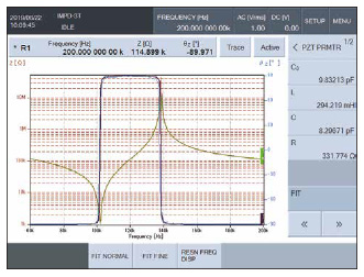
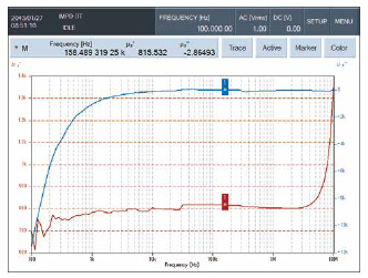
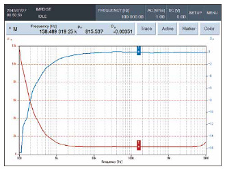
RESONANT FREQUENCY TRACKING FUNCTION
During measurement of samples with resonance, this function automatically tracks the measurement frequency with the sample resonant frequency. Measurement can always be conducted to match the resonant frequency. A convenient function for continuous measurements close to the resonant frequency of piezoelectric devices.
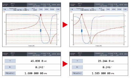
Resonant
frequency changes (1.6 kHz to 1.5858 kHz),
tracks automatically
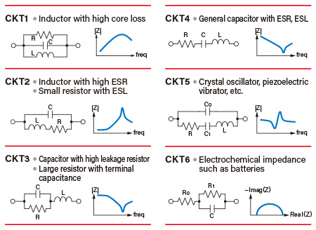
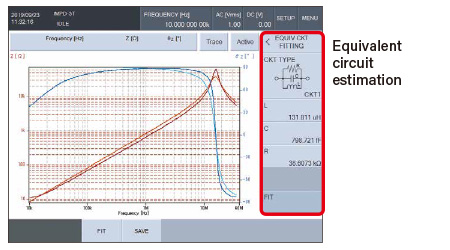
EQUIVALENT CIRCUIT ESTIMATION FUNCTION
A
function that determines the LCR element value
(values for impedance, electrostatic capacitance and
resistance) by applying the impedance characteristics acquired with frequency
sweep measurements to equivalent circuit models.
The following 6 models are included.
Equivalent circuit model
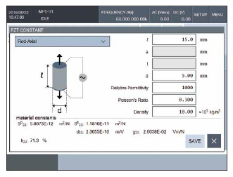
PIEZOELECTRIC CONSTANT CALCULATION FUNCTION
Function that measures frequency-impedance characteristics of piezoelectric ceramics to calculate the electromechanical coupling factor, piezoelectric constant and others.
∗JEITA standard-compliant method “EM-4501A Electrical test methods for piezoelectric ceramic vibrators”.
Measurement results
Constant calculation
RELATIVE PERMITTIVITY MEASUREMENT
Sample dimensions and other information is set in advance, to calculate and display the complex relative permittivity from impedance measurement results (Cp, Rp).
● Relative permittivity εs
● Relative permittivity, real εs’
● Relative permittivity, imaginary εs”
● Loss ratio Dε
εs’−εs”
εs−Dε
RELATIVE MAGNETIC PERMEABILITY MEASUREMENT
Sample dimensions and other information are set in advance, to calculate and display the complex relative magnetic permeability from impedance measurement results (Ls, Rs).
● Relative magnetic permeability µs
● Relative magnetic permeability, real µs’
● Relative magnetic permeability, imaginary µs”
● Loss ratio Dµ
µs’−µs”
µs−Dµ
COMPARATOR/HANDLER INTERFACE Ideal for production lines!
Measurement up to 0.5 ms/point
to shorten takt time
Also with parts selection function!!
The comparator is a function that allows samples to be sorted or passed/rejected by setting the criteria range in advance based on measurement results.
Comparator setting screen
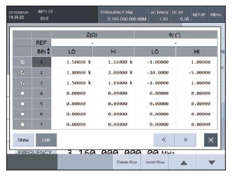
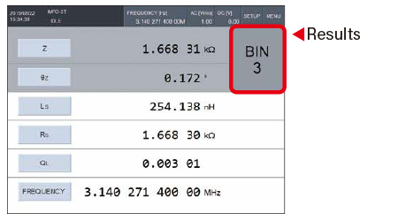
Bin sorting
Sorts results in up to 14 categories.
Limit sorting
Determines pass/reject based on the set range.
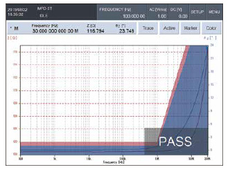
Zone sorting
Determines pass/reject based on sweep measurement results in two-dimensions, X axis (sweep parameter) and Y1, Y2 axes (measurement results).
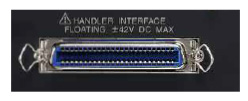
Handler interface
The comparator criteria results can be output to the handler interface connector. Connect a parts handler to create an automated parts sorting system.
EXTERNAL REFERENCE CLOCK
An
external 10 MHz clock signal can be used as the reference clock. Using a
reference clock with a higher precision than the internal reference clock helps
to improve the measurement frequency accuracy and stability.
The use of a reference clock common with other devices also allows for the same
frequency accuracy.
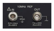
Mounted
on rear panel
MEMORY CONTROL
Measurement conditions and measurement data can be saved and loaded onto the internal memory or USB memory storage.
● Electrochemical impedance characteristics measurements
Functions cover a range of measurements of electrochemical impedance characteristics, such as battery internal impedance measurements.
· ● Ultra-low frequencies from 10 µHz
· ● Phase slope compensation function to
limit measurements being affected
by potential changes due to charging and discharging
· ● 0° SYNC function changes the
measurement frequency by 0° phase,
for zero charge transfer before and after measurements.