 |
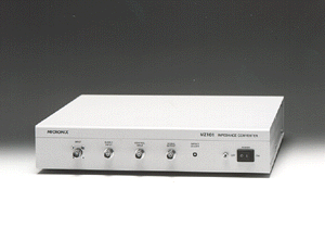
MZ101 Impedance converter for measuring ultra high impedance circuit
¡@
 |
¡@
Functions and characteristics
![]() Ultra high impedance input : more than 1013ohm
Ultra high impedance input : more than 1013ohm
![]() Ultra low input leakage current : less than 1pA
Ultra low input leakage current : less than 1pA
![]() Broad voltage dynamic range : 20Vp-p
Broad voltage dynamic range : 20Vp-p
![]() Short rise time : 350ns
Short rise time : 350ns
![]() Effective for voltage holding ratio measurement of
LCD 's (liquid crystal display unit) because of provision
Effective for voltage holding ratio measurement of
LCD 's (liquid crystal display unit) because of provision
of SUPPLY INPUT (power source input terminal).
![]() The input terminal is of a 3 terminal structure, and a circuit that compensates
for (cancels) insulation resistance and capacitance
The input terminal is of a 3 terminal structure, and a circuit that compensates
for (cancels) insulation resistance and capacitance
of the measuring cable is equipped with.
![]() The input circuit unit is accommodated in a case controlled at constant low
temperature, and the input resistance and input leakage
The input circuit unit is accommodated in a case controlled at constant low
temperature, and the input resistance and input leakage
current characteristics are hardly affected by the ambient temperature.
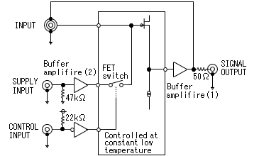
MZ101 has characteristics of ultra high input resistance and ultra low input leakage current. It is a non-conventional impedance converter of a new type that materializes wide input voltage range and high frequency characteristics. It has the performance that input resistance is more than 1013ohm, input leakage current is within 1pA, measuring input voltage range is 20Vp-p, frequency characteristic is 1MHz and output resistance is 50ohm. Therefore, when MZ101 is applied to the waveform measurement of a high impedance circuit network, it is able to measure without influencing the measuring circuit. Furthermore, a power source terminal for impressing voltage to the input terminal is provided, an electronic switch (FET is used) between both terminals, and switching can be performed by the signal at the switch control terminal. MZ101 exhibits superior power in the measurement and evaluation of electronic parts of high impedance systems such as the measurement of insulation resistance of capacitor and the measurement of voltage holding ratio of LCD.
Theory of operation
MZ101
is composed of FET source follower, buffer amplifier (1) and supply input
voltage ON / OFF switch (FET switch). Each FET is of ultra low leakage current,
and in addition, devices connected to the input signal line are accommodated in
a case controlled at constant low temperature. Therefore, any leakage current is
suppressed to a minimum level and variation caused by temperature is minor.
Buffer amplifier (1) are inserted for correcting the gain of the FET source
follower and for providing output buffer function. The output of buffer
amplifier (1) is connected to the inside shield of the input terminal, for the
purpose of canceling the influence of the measuring cable.

¡@
¡@
¡@
¡@
¡@
¡@
¡@
¡@
¡@
¡@
¡@
Applications
1. High impedance circuit network measurement
For
high impedance circuit network measurement, the circuit is adversely affected if
a probe of the oscilloscope is used because input resistance of the probe is as
low as 10Mohm.
When MZ101 is used, however, the measuring system will not be adversely affected
because its input resistance is 1013ohm or higher. At this time, connect the
HIGH terminal of the measuring cable to the measuring point, LOW terminal to the
circuit ground and GUARD terminal to the shielding case insulated from the
circuit ground. Furthermore, keep SUPPLY INPUT terminal and CONTROL INPUT
terminal open without connecting anything.
¡@
2. Capacitor's insulation resistance measurement
Sample
hold capacitor and integrator capacitor require low losses, i.e., high
insulation resistance. As the method for measurement of insulation resistance
(parallel resistance) of a capacitor, place the capacitor to be measured in a
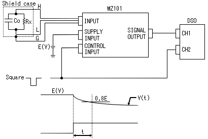
shielding case and connect the measuring cable as diagram shown. Connect the DC
power source to SUPPLY INPUT terminal and input the TTL level square wave to
CONTROL INPUT terminal. In addition, make connection to the digital oscilloscope
(DSO) as diagram shown.
While the square wave input to the CONTROL INPUT terminal is of a low level, the
internal FET switch is ON, and capacitor Co to be measured is charged to E (V)
of the DC power source. When the level is changed to a high level later, the FET
switch is OFF and Co begins to discharge. This discharge curve is measured with
the DSO. For instance, when voltage V (t) lowered by 20% from E (V), and time t
are measured, the insulation resistance can be calculated using a numerical
expression.
¡@

¡@
¡@
¡@
¡@
¡@
¡@
¡@
¡@
¡@
¡@
¡@
¡@
¡@
¡@
¡@
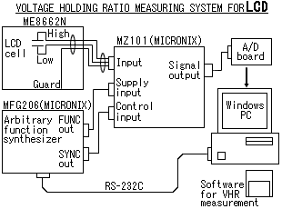
3. Voltage holding ratio measuring system for LCD
The voltage holding ratio of LCD can be measured by the system composed of MZ101,
shielding box ME8662N , arbitrary function synthesizer MFG206, A / D board and PC as shown below.
¡@

¡@
¡@
¡@
¡@
¡@
¡@
¡@
¡@
¡@
¡@
¡@
¡@
¡@
| Main specifications | |
| Input terminal | |
| Input resistance | more than 1013ohm |
| Input leakage current | less than 1pA |
| Input capacitance | less than 10pF |
| Rise time | less than 350ns @ within ¡Ó7.5V input and
50ohm load less than 450ns @ within ¡Ó10V input and 50ohm load |
| Frequency response | 1MHz (-3dB) @ 5Vp-p sinewave input |
| Gain between input and output | 1.0 ¡Ó2% @ no load |
| Measurement input voltage range | within ¡Ó10V |
| Input damage level | ¡Ó13V (AC + DCpeak) max |
| Connector | connector included guard |
| Supply input terminal | |
| Input resistance | approx. 47ohm |
| Measurement input voltage range | within ¡Ó10V |
| Input damage level | ¡Ó20V (AC + DCpeak) max |
| Connector | BNC connector |
| Charge time | less than 30µs @ 1300pF load and 12V supply |
| Control input terminal | |
| Signal level | TTL level (active low) |
| Input damage level | ¡Ó20V (AC + DCpeak) max |
| Connector | BNC connector |
| Signal output terminal | |
| Output offset voltage | available adjustment at front panel |
| Output impedance | 50ohm (nominal) |
| Connector | BNC connector |
| General | |
| Operating temperature | 0 to 40¢XC (Guaranteed at 23 ¡Ó10¢XC) |
| Operating humidity | less than 40¢XC / 90%RH (Guaranteed at less than 33¢XC / 80%RH) |
| Warmup time | more than 30min. |
| Power supply | AC90V to 127V, 50 / 60Hz |
| Dimensions | 56 (H) ¡Ñ 300 (W) ¡Ñ 300 (D) mm |
| Weight | approx. 2.5kg |
| Accessories | Instruction manual (1pc), Fuse (2pcs), Measuring cable (1pc), Power cable |
|
|
|
Products list | brand | Model No. | Home