| |
Contact
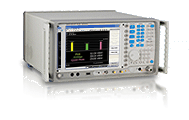 |
EMI Test Receiver
 |
| |
| |
| LIG Nex1’s EMI Receiver verifies every EMI standard in full compliance with CISPR in the frequency range from 3Hz to 3GHz. Experience the LIG Nex1’s EMI Receiver certified in the fields of EMI Conducted and Radiated Emission |
| |
 |
|
 |
| |
Commercial standards
 CISPR11.22 CISPR11.22
 EN55011.55022 EN55011.55022
 VDE0872.0879 VDE0872.0879
 ANSI-C63.4 ANSI-C63.4
 FCC15, 18 FCC15, 18
 EACL1.8 EACL1.8 |
|
 |
|
 |
|
|
 |
|
 |
| |
Military standards
 VG95370.95377 VG95370.95377
 DEF-STAN49.41 DEF-STAN49.41
 GAM-EG13 GAM-EG13
 MIL-STD-461E MIL-STD-461E
|
|
 |
|
 |
|
|
|
|
|
| Main Uses |
| |
Full Compliance for EMI standards (CE, RE)
LIG Nex1’s EMI Receiver is a specialized equipment designed for EMI full compliance conforming to the international EMI standard, CISPR16-1-1. The standard pre-selector for full EMI compliance enhances the reliability of the test result by removing the interferences among the signals in the required bands, and precisely measuring the noise value of the EUT. Also, The standard tracking generator fulfills alignment of the pre-selector as well as scalar network analysis, and NSA. |
 |
Debugging for EMI R&D, Lab
During the EMI test , users can detect the exact weak points of the EUT under EMI environment specified on the EMI standards of each country, and find how to improve the design by testing its RF characteristics precisely in Spectrum Analyzer mode. LIG Nex1’s EMI receiver provides powerful spectrum analyzer performance and personalities such as Spurious Emission, Phase Noise, TOI, CCDF, and etc. basically so that users can analyze the exact weak points, and improve them |
 |
EMI Pre-Test for R&D, Manufacturing
In the fields of R&D and manufacturing for RF equipment, module, parts, and etc., LIG Nex1’s EMI receiver enables users to save high costs of the EMI Test and debugging that is regularly fulfilled by the certified EMI lab or institution on the process of development & manufacturing, and reduce the trouble shooting time. Also, users can get the reliable EMI test results under the variously simulated test environments by changing the field correction factors using the convenient correction factor table. |
 |
NSA (Normalized Site Attenuation); Environment test in Chamber
Monitoring the test environment such as antenna, turn table, and etc. in the test house (Chamber) specified in CISPR 16-1-4 automatically in real time, and correct it according to the gathered VSWR data. Users can optimize EMI test environment in the test house before starting EMI Test. |
| |
| Features and Performance |
| Leading in Features |
| |
 |
Debugging in Spectrum Analyzer mode (Scan mode/Spectrum Debugging Mode) |
 |
 |
Maximum 6 sub-ranges, set frequency range, step size, Bandwidth, Measure Time etc. by ranges |
 |
 |
Display traces and limit lines of 3 detectors, Quasi-peak, Peak, Average simultaneously |
 |
 |
All Commercial EMI Standards such as KN, EN, FCC etc based on CISPR |
 |
 |
Amplitude Correction functions: Antenna, Cable, User’s own factors |
 |
 |
CISPR verification mode for EMI Lab, Institution |
 |
 |
X Scale Log/Linear conversion function |
 |
 |
Standard Built-in Pre-selector (14 pre-selection filters) for precise measurement |
 |
 |
Standard Built-in Tracking Generator for Pre-selector alignment and Normalized Site Attenuation in Test House |
 |
 |
Standard Built-in Pre-Amplifier (Gain : 20dB nominal @ 1kHz ~ 3GHz) |
 |
 |
10.4” TFT Wide Screen LCD |
 |
 |
System OS: Windows XP Professional |
 |
 |
Remote control : GPIB, RS-232C, LAN Interface (Standard) |
 |
 |
Labview, Labwindows, CVI Driver |
 |
 |
Installable Printer Driver (XP) |
 |
 |
Optional built-in Pre-Amplifier (Gain : 30dB nominal @ 100MHz ~ 3GHz) |
 |
 |
Optional built-in C/W Signal Generator (1.3GHz/3.3GHz/6.6GHz) |
| |
| Performance |
| Item |
Specifications |
Frequency range |
3Hz ~ 3GHz/26.5GHz(Resolution 1Hz ) |
Phase Noise |
-112dBc (-115 typical ) at 10kHz offset |
TOI |
+20dBm (typical) @ 100MHz ~ 26.5GHz?? (Pre-amp off) |
SHI |
+80dBm nominal @ 1.5 GHz to 26.5 GHz?? (Pre-amp off) |
| TOI |
Typical +20dBm (@ 100MHz ~ 1GHz, Pre-amp off) |
| DANL |
-166[dBm/Hz] typical @ 100MHz to 3GHz (Preselector on, preamp2 on) |
| -168[dBm/Hz] typical @ 3GHz to 16GHz (Preselector on, preamp2 on) |
Trace detectors |
3 traces Mode : Normal, peak, sample, negative peak,
log power average, RMS average, voltage average, Quasi-peak |
Frequency response |
± 1.0dB ~± 1.5dB at 3.0GHz to 6.4GHz? (Preselector on, preamp2 on) |
± 1.5dB ~± 2.5dB at 6.4GHz to 26.5GHz? (Preselector on, preamp2 on) |
Total Measurement Uncertainty |
+1.0dBm (Preselector on) |
+0.7dBm (Preselector off) |
|
| |
| High Reliability in Measurement |
| Item |
Specifications |
| RBW |
Sweep Mode
(3dB bandwidths) |
1 Hz to 5 MHz (1-2-3-5 sequence) , Shape factor <5 |
Scan Mode
(6dB bandwidths) |
10Hz,100Hz, 200Hz, 1KHz, 9KHz, 10KHz, 100KHz, 120KHz, 1MHz, 1MHz Impulse |
| VBW |
1 Hz to 3 MHz, none (1-2-3-5 sequence) |
| Sweep time |
Sweep Mode
(Spectrum Analyzer) |
Zero span: 1 us to 2000 sec, ±0.5% |
Scan Mode (EMI Receiver) |
Span ≥ 10Hz: 10 ms to 2000 sec, ±0.5% nominal |
RF Attenuator |
0dB ~ 55dB (5dB Step) |
Demodulation |
?AM demodulation depth(~ 100%) |
Measurement |
ACR, Phase Noise, CCDF, TOI, Spurious Emission,
Spectrum Emission ? Mask 등 강력한 RF 측정 기능 지원
|
Residual Response |
-95dBm@1MHz ~3GHz ( Input termed, 0dB Attenuation) |
|
| |
|
 |
|
| Main Feature |
 |
|
|
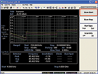
 Scan mode Scan mode |
- Base mode for EMI measurement
- Display Peak, Average, Quasi-peak 3 detectors simultaneously
- Display separate wave forms by detectors
- Scanning according to the set value in range of the configuration table
- Scan from 20 Hz to 3GHz
Support 6dB BW Filter (200Hz, 9kHz, 120kHz, 10Hz, 100Hz, 1kHz,
10kHz, 100kHz, 1MHz, 1MHz Impulse)
- Precise measurement of low level signals with a built-in pre-amplifier |
|
| |
 |
|
|
 EMC Configuration Table EMC Configuration Table |
- Set maximum 6 Ranges for customer’s own purposes
- Set Start/ Stop frequency, Step, Measure time,
Measure bandwidth, built-in pre-amp, Attenuator by ranges
- Display all factors of scan information simultaneously
- Antenna, Cable, Other, User’s factors |
|
| |
 |
|
|
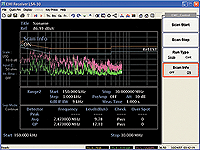
 Scan Information Scan Information |
- Display the detailed test results on scanning
- Display the set value of the selected range
- The current position and level by detectors
- Display pass or fail on the set limit line
- Quantities of the points over the limit line |
|
| |
 |
|
|
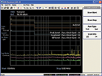
 Limit Line Setting Limit Line Setting |
- Set limit lines by detectors (Peak, Quasi-peak, Average)
- Alarm sound when the value is over the limit line
- Various limit lines conforming to the world EMI standard |
|
| |
 |
|
|
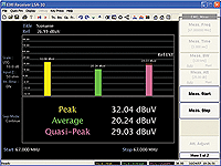
 CISPR verification mode CISPR verification mode |
- Peak, Average, Quasi-peak detection in a selected frequency
- Bar-graph display for 3 detectors that help a user see the results
- Set an attenuator according to the level of signal
- CISPR-16 standard |
|
| |
 |
|
|
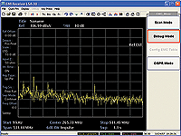
 Debug mode Debug mode |
- Display information of a noise or signal detected in scan mode
under the Spectrum Analyzer mode in details
- This mode sweeps just as Spectrum Analyzer
- Sweep from 20Hz to 3GHz |
|
| |
 |
|
|
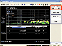
 Edit limit line Edit limit line |
- Draw and edit limit lines for any user’s needs
- Different colors of lines for better view
- Save, load, edit each Detector
- Maximum 200 points available |
|
| |
 |
|
|
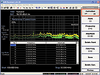
 Edit correction factors Edit correction factors |
- Edit various correction factors for any user’s purposes
- Compensate gain and loss by amplifier. In case of gain, input
(-) value, and in case of loss, input (+) value
- Maximum 8,192 point settings
- In case, the correction value is one, compensate the whole ranges
- Correction between each point by linear interpolation technically |
|
| |
 |
|
|
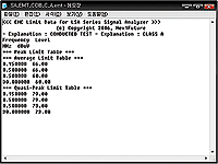
 Real data for limit line Real data for limit line |
- Save and load the test results into .EMT file
- Available general text editor (notepad, wordpad, word)
- Edit with the Microsoft excel program |
|
|
| |
 |
|
|
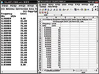
 Real data for antenna Real data for antenna |
- Save and Load the test results into .ANT file
- Available general text editor (notepad, wordpad, word)
- Edit the test results with Microsoft Excel program |
|
|
|
|
|


