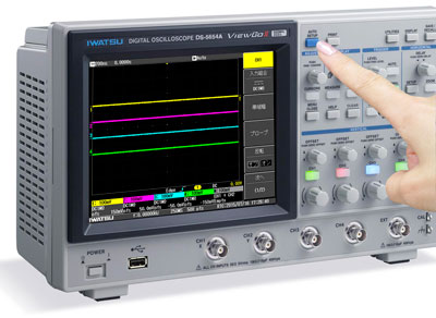
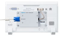
Digital oscilloscope "ViewGoⅡ" DS-5600A series
|
DS-5600A series Band |
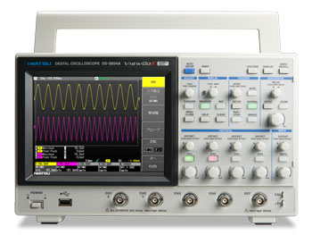

DS-5600A Series New function
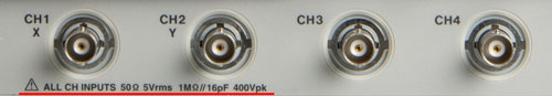
All models of DS-5600A support 50 ohm input
It can support a wide variety of probes.
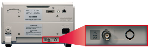
Equipped with AUX OUT output terminal as standard
In addition to the trigger signal output, the Pass/Fail judgment function can be output when the result is Pass or Fail.
When measured at a sampling rate lower
than the maximum sampling rate, the data captured at the maximum sampling
rate can be averaged to capture the waveform, reduce random noise, and improve the vertical
resolution equivalently to a maximum of 12 bits. |
|
|
|
Normal sampling |
High Resolution 12 bits resolution equivalent |
Table
the current vertical resolution in the |
|
Expanded averaging count
The number of averaging settings has been expanded from 256 to 65536 (maximum). A periodic random signal can be effectively reduced from repeated measured signals. ・When the amplitude ratio of signal (triangular
wave: 50Hz) and noise (random) is 1:1 |
|
|
|
Averaging process OFF |
Averaging processing ON (averaging count 32768 times) |
Displays the number of processing during the averaging calculation processing. |
|
Auto setup disable switching function
Prevents the panel settings from being updated even if the "AUTO SET" button is pressed by mistake. |
|
|
|
|
|
Specifications
DS-5654A |
DS-5652A |
DS-5634A |
DS-5632A |
DS-5624A |
DS-5622A |
DS-5614A |
DS-5612A |
|||||||||||||
Frequency band (-3dB) |
500MHz |
350MHz |
200MHz |
100MHz |
||||||||||||||||
Rise time |
750ps |
1 ns |
1.75ns |
3.5ns |
||||||||||||||||
Number of input channels |
Four |
2 |
Four |
2 |
Four |
2 |
Four |
2 |
||||||||||||
Maximum sampling rate |
2GS/s (when channels are combined), 1GS/s (when all channels are used) |
|||||||||||||||||||
Equivalent sampling rate |
100GS/s |
|||||||||||||||||||
Peak detection resolution |
1 ns |
|||||||||||||||||||
Averaging function |
2 to 65536 times (power of 2 step) |
|||||||||||||||||||
Averaging |
Display the number of executions on the screen |
|||||||||||||||||||
Memory length |
5M points/ch (when 2 channels are combined), 2.5M points/ch (all channels) |
|||||||||||||||||||
Vertical resolution |
8 bits (when high-resolution calculation is effective: maximum 12 bits) |
|||||||||||||||||||
Vertical resolution display function |
Display resolution bits |
|||||||||||||||||||
Input voltage range |
2mV/div ~ 10V/div (1MΩ) |
|||||||||||||||||||
Offset voltage |
2mV/div to 50mV/div: ±1V, 50.2mV/div to 500mV/div: ±10V, 502mV/div to 10V/div: ±100V |
|||||||||||||||||||
DC gain accuracy |
±(1.5% + 0.5% full scale) |
|||||||||||||||||||
Maximum input voltage |
±400 Vpeak I (1 MΩ), 5 Vrms (50 Ω) |
|||||||||||||||||||
Band limiting filter |
Analog system: 100MHz, 20MHz, 2MHz, 200kHz |
Analog system: 20MHz, 2MHz, 200kHz |
||||||||||||||||||
Digital method: LPF, HPF or SMA selected, channel independent |
||||||||||||||||||||
Input coupling |
GND, DC 1MΩ, AC 1MΩ, DC 50Ω |
|||||||||||||||||||
Input impedance |
1MΩ±1%//16pF, 50Ω±1% |
|||||||||||||||||||
Probe sense |
Automatic detection: 1:1、10:1、100:1、1000:1 |
|||||||||||||||||||
Time axis range |
500ps/div ~ 50s/div |
1ns/div ~ 50s/div |
2ns/div ~ 50s/div |
5ns/div ~ 50s/div |
||||||||||||||||
Standard probe |
SS-101R (Standard attachment for the number of channels) |
SS-0130R (Standard attachment for the number of channels) |
||||||||||||||||||
Roll mode |
50ms/div ~ 50s/div (100kS/s max) |
|||||||||||||||||||
Clock accuracy |
±10 ppm |
|||||||||||||||||||
Trigger function |
||||||||||||||||||||
Trigger function |
Edge, Edge Alternate, Edge OR, Pulse
Count, Pulse Width, Period, Missing, TV, Pattern (OR, NOR, AND, NAND), |
|||||||||||||||||||
TV trigger (standard) / |
NTSC, PAL, Custom / up to 3000 / 1, 2, 4, 8 |
|||||||||||||||||||
Pulse number trigger setting range |
1 to 9999 events |
|||||||||||||||||||
Pulse width trigger time setting range |
15ns ~ 50s |
|||||||||||||||||||
Period trigger time setting range |
40ns ~ 50s |
|||||||||||||||||||
Dropout |
50ns ~ 50s |
|||||||||||||||||||
Pattern trigger |
OR, NOR, AND, NAND |
|||||||||||||||||||
Trigger source/ |
All channels / HIGH, LOW, Don't Care / All channels independent setting |
|||||||||||||||||||
Serial trigger UART |
|
|||||||||||||||||||
Serial trigger SPI |
|
|||||||||||||||||||
Serial trigger I 2 C |
|
|||||||||||||||||||
Trigger source |
All channels, EXT (±0.5V), EXT10 (±5.0V), line |
|||||||||||||||||||
Trigger slope/ |
Positive, negative/AC, DC, high frequency rejection, low frequency rejection, noise rejection |
|||||||||||||||||||
Display/resolution |
||||||||||||||||||||
Display/resolution |
7.5-inch color TFT LCD (touch screen) / VGA: 640 × 480 pixels |
|||||||||||||||||||
Display format |
YT, XY, XY trigger |
|||||||||||||||||||
Vector connection |
Interpolation display between sample points, dot display |
|||||||||||||||||||
Analog |
Monochromatic gradation display, spectrum display |
|||||||||||||||||||
Persistence |
100ms, 200ms, 500ms, 1s, 2s, 5s, 10s, infinity |
|||||||||||||||||||
Internal waveform storage |
5 waveforms |
|||||||||||||||||||
Save front panel settings |
5 settings can be stored in the internal memory, USB memory |
|||||||||||||||||||
AUTO SETUP function |
Enabled/disabled configurable |
|||||||||||||||||||
Parameter measurement, cursor, zoom, calculation, replay function |
||||||||||||||||||||
Parameter measurement |
Maximum value, minimum value, peak peak, RMS value, cycle RMS value, average value, cycle average value, top, base, top-base, rising overshoot, falling overshoot, rising time 20-80%, falling time 80-20%, rise time 10-90%, fall time 90-10%, frequency, period, pulse number (positive), pulse number (negative), pulse width (positive), pulse width (negative), duty ratio , Integration, skew (positive/negative), skew @ level |
|||||||||||||||||||
Simultaneous measurement/ |
Maximum 4 parameters/maximum value, minimum value, number of measurements |
|||||||||||||||||||
Logging item, output destination |
Time, parameter measurement result
(conditions A, B, C, D), Pass/Fail judgment result |
|||||||||||||||||||
Pass/Fail |
Judgment mode: Parameter judgment or
mask judgment, judgment result: USB save, BEEP sound, |
|||||||||||||||||||
cursor |
Time, amplitude, time & amplitude, cursor value |
|||||||||||||||||||
zoom |
Press the Zoom button on the front panel to display the enlarged waveform in another grid |
|||||||||||||||||||
Math function |
Addition/subtraction/multiplication/differential/integration/FFT (up to 8k points, rectangular/hanning/flat-top
window function) From |
|||||||||||||||||||
Rescale/Unit conversion |
a*x+b (x: input voltage, a, b: user defined)/volt, ampere, watt, °C, no display |
|||||||||||||||||||
Replay |
Automatically record waveforms, save up to 2048 waveforms, replay possible |
|||||||||||||||||||
Frequency counter |
6 digits |
|||||||||||||||||||
interface |
USB 2.0 HS compatible (device,
host), LAN (100Base-TX), |
|||||||||||||||||||
AUX OUT |
Switchable between trigger output and pass/fail judgment output |
|||||||||||||||||||
Save waveform data |
Save to USB memory in binary, ASCII, Mathcad, Math (ASCII), Math (Mathcad) |
|||||||||||||||||||
Hardcopy output |
Save to USB memory in TIFF, BMP, PNG
(transparency compatible) format |
|||||||||||||||||||
Calibration signal output |
Square wave 1kHz, 3Vp-p |
|||||||||||||||||||
Power/power consumption |
AC100V ~ 240V (50Hz / 603Hz), AC100V ~ 120V (400Hz) / 95VA max (60W max) |
|||||||||||||||||||
Dimension/Mass weight |
About 330Wx190Hx124D mm / About 3.7kg |
|||||||||||||||||||
Environmental condition |
||||||||||||||||||||
Performance guarantee temperature |
10 ~ 35 ℃ |
|||||||||||||||||||
Operating temperature/humidity/altitude |
Temperature 0-40°C / Humidity
5-80%RH ≤ 30°C (no
condensation), |
|||||||||||||||||||
Standard accessories |
||||||||||||||||||||
Probe (number of channels), power cord (1), front panel cover (1), instruction manual (CD-ROM) (1), user's guide (1) |
||||||||||||||||||||
option |
||||||||||||||||||||
AUX IO CH1/CH2 output |
AUX IO1: Output CH1 input signal with offset voltage added, AUX IO2: Output CH2 input signal with offset voltage added |
|||||||||||||||||||
AUX IO CH1 output |
AUX IO1: CH1 input signal with offset voltage output |
|||||||||||||||||||
GPIB interface |
GPIB: IEEE488.2 |
|||||||||||||||||||
Power supply for probe |
Two power supplies for our active probe |
|||||||||||||||||||
Dedicated option
■ Dedicated option
|
GP-IB interface *Factory option |
|
|||||||||||||||
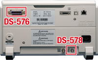
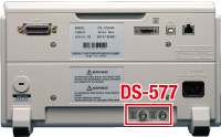
DS-577 AUX I/O
option (CH1/CH2 output) *Factory option
|
||||||||||||||||
DS-578 AUX I/O
option (CH1 output) *Factory option
|
||||||||||||||||
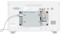
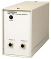
DS-579 Probe power option
|
|
|||||||||||||||
IE-1226 made to order VGA Video OUT option You can output the waveform screen to an external display. *DS-579 cannot be used after IE-1226 is installed. |
|
|||||||||||||||
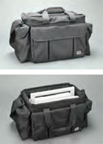
Carrying bag *Commercial item, multipurpose bag |
|
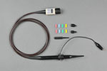
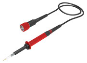
■ Standard probe
SS-0130R Frequency
bandwidth: DC to 200MHz Compatible
models: |
|
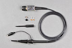
SS-101R (Discontinued) Frequency
bandwidth: DC to 500MHz Compatible
models: |
|
SS-0150R (successor probe to SS-101R) Frequency
bandwidth: DC to 500 MHz Compatible
models: |
|
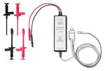
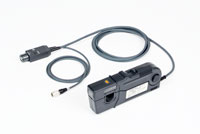
■High voltage differential probe
|
Frequency
bandwidth: DC to 100MHz |
|
DS-579 Probe power option ViewGoⅡ dedicated probe power supply unit Compatible probes: SFP-5A/4A, SS-270/260/250/240A/240, SS-320 |
|
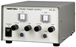
PS-25 Power supply for SFP-5A/4A/SS-320 |
|
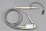
■ Active probe
|
Frequency
bandwidth: DC to 1 GHz (for probe only) |
|
|
Frequency
bandwidth: DC to 800MHz *1 |
|
DS-579 Probe power option ViewGoⅡ dedicated probe power supply unit Compatible probes: SFP-5A/4A, SS-270/260/250/240A/240, SS-320 |
|
|
Power supply for SFP-5A/4A/SS-320 |
|
■High voltage probe
PHV 1000-RO Attenuation
ratio: 100:1, Input RC: 50 MΩ 7.5 pF |
|
|
DC-50MHz, DC-30kV, pulse 40kV |
|
|
DC-50MHz, DC-60kV, pulse 80kV |
|
*Please select the high voltage probe after confirming the derating characteristics.
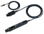
■ Current probe
Rogowski coil current probe SS-28xA series Frequency
band: fL to 30MHz Sensor part temperature range: -40℃ to 125℃ |
|
Rogowski coil current probe SS-29x series Frequency
band: S type-fL to 20MHz, L type-fL to 10MHz Sensor part temperature range: -40℃ to 125℃ |
|
|
Frequency bandwidth: DC to 100MHz *1 (maximum 30Arms) |
|
|
Frequency bandwidth: DC to 50MHz *1 (max. 30Arms) |
|
|
Frequency bandwidth: DC to 10MHz *1 (up to 150Arms) |
|
|
Frequency bandwidth: DC to 2MHz *1 (maximum 500Arms) |
|
DS-579 Probe power option ViewGoⅡ(DS-5500) series dedicated probe power supply unit Compatible probe: SFP-5A/4A, SS-270/260/250/240A/240 |
|
|
Power supply for current probe |
|
*1 For a single probe
* Calibration certificate, traceability system diagram, and inspection report will be charged separately.