MZ1800 VHR Measuring System
Measuring Voltage Holding Ratio of LCD
¡@
When researching and developing LCD (liquid crystal display) of TFT type, it is the most important and significant factor to measure and evaluate the voltage holding ratio (VHR) of LCD cell.¡@
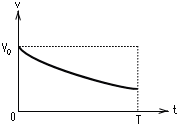
[method 1] Area comparison method
VHR is calculated based on the following equation.
![]()
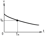
[method 2] Effective value method
VHR is calculated based on the following equation.
![]()
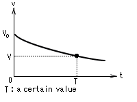
[method 3] Droop value method
VHR is calculated based on the following equation.
![]()
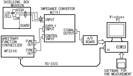
VHR measuring system consists of four components of Impedance Converter MZ101 as a signal conditioner, SHIELDING BOX ME8662N to protect a LCD cell against noise, Arbitrary Function Synthesizer MFG206 generating supply voltage and timing pulse and windows PC in which an A / D converter is installed.
¡@
1. Impedance Converter MZ101
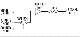
Input is guard-shielded as shown below. Accordingly, VHR measurement of LCD cell is not affected by the stray
capacity of a measuring cable.
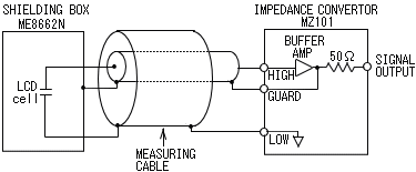
MZ101 also has a switch to supply the voltage to LCD cell as shown
below.
2. SHIELDING BOX ME8662N
SHIELDING BOX ME8662N is necessary to protect LCD cell against noise
and to measure VHR stably.
3. Arbitrary Function Synthesizer
MFG206
MFG206 operates as a voltage source which charges LCD cell and as a
control signal source to control a switch
in MZ101. Timing diagram is shown below. FUNC OUT and SYNC OUT of MFG206 are connected to SUPPLY
INPUT and CONTROL INPUT of MZ101 with two coaxial cables.
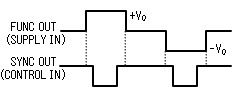
The supply voltage V0 can be changed
by using AMPL (Amplitude) of MFG206. The maximum value of V0
is 10 volts.
4. Windows PC with A / D converter
The A / D converter converts a waveform output
at SIGNAL OUTPUT of MZ101 to 16 bits digital data and
transfers these data Windows PC.
SOFTWARE FOR VHR MEASUREMENT controls MFG206, displays a waveform from MZ101 and calculates VHR.
¡@
| MZ101 Specifications | |
| Input terminal. | |
| Input resistance | more than 1013ohm |
| Input leakage current | less than 1pA |
| Input capacitance | less than 10pF |
| Rise time |
less than 350ns @ within ¡Ó7.5V input and
50ohm load less than 450ns @ within ¡Ó10V input and 50ohm load |
| Frequency response | 1MHz (-3dB) @ 5Vp-p sine wave input |
| Gain between input and output | 1.0 ¡Ó2% @ no load |
| Measurement input voltage range | within ¡Ó10V |
| Input damage level | ¡Ó13V (AC + DCpeak) max |
| Connector | connector included guard |
| Supply input terminal | |
| Input resistance | approx. 47ohm |
| Measurement input voltage range | within ¡Ó10V |
| Input damage level | ¡Ó20V (AC + DCpeak) max |
| Connector | BNC connector |
| Charge time | less than 30µs @ 1300pF load and 12V supply |
| Control input terminal. | |
| Signal level | TTL level (active low) |
| Input damage level | ¡Ó20V (AC + DCpeak) max |
| Connector | BNC connector |
| Signal output terminal. | |
| Output offset voltage | available adjustment at front panel |
| Output impedance | 50ohm (nominal) |
| Connector | BNC connector |
| General. | |
| Operating temperature | 0 to 40¢XC (Guaranteed at 23 ¡Ó10¢XC) |
| Operating humidity | less than 40¢XC / 90%RH (Guaranteed at less than 33¢XC / 80%RH) |
| Warmup time | more than 30min. |
| Power supply | AC90V to 127V, 50 / 60Hz |
| Dimensions | 56 (H) ¡Ñ 300 (W) ¡Ñ 300 (D) mm |
| Weight | approx. 2.5kg |
| Accessories | Instruction manual (1pc), Fuse (2pcs), Measuring cable (1pc), Power cable (1pc) |
|
|
|
Products list | brand | Model No. | Home